For 1990-2009 cars only
Removal Procedure
- Remove the driver side instrument panel sound insulator. Refer to Instrument Panel Insulator Replacement in Instrument Panel, Gages and Console.
- Remove the driver side front floor air outlet duct.
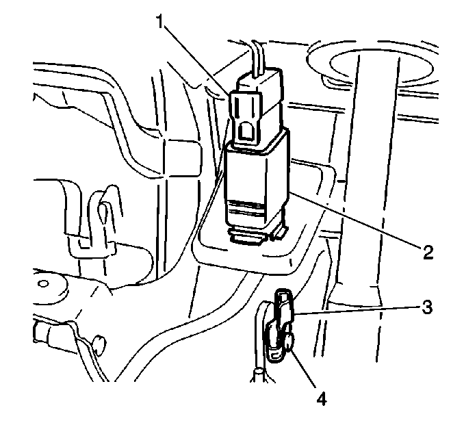
- Remove the wiring harness connector (1) from the stoplamp switch (2).
- Use angled pointed pliers to compress both the locking tabs to remove the stoplamp switch.

Installation Procedure
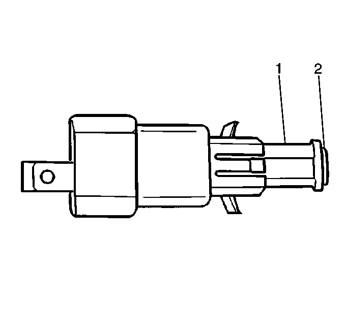
- Pull both the actuating pin (2) and the retaining collar (1) out of the stoplamp switch to the full extended position of about 17 mm (2/3 in).
- Engage the tangs on the stoplamp switch with the brake pedal bracket to install the stoplamp switch to the brake pedal bracket.
- Install the wiring harness connector (1) to the switch (2).
- Install the driver side front floor air outlet duct.
- Install the driver side instrument panel sound insulator. Refer to Instrument Panel Insulator Replacement in Instrument Panel, Gages and Console.


Important: Do not push the actuating pin into the stoplamp switch. The actuating pin self-adjusts to the brake pedal position when the brake pedal returns to the at-rest position.
