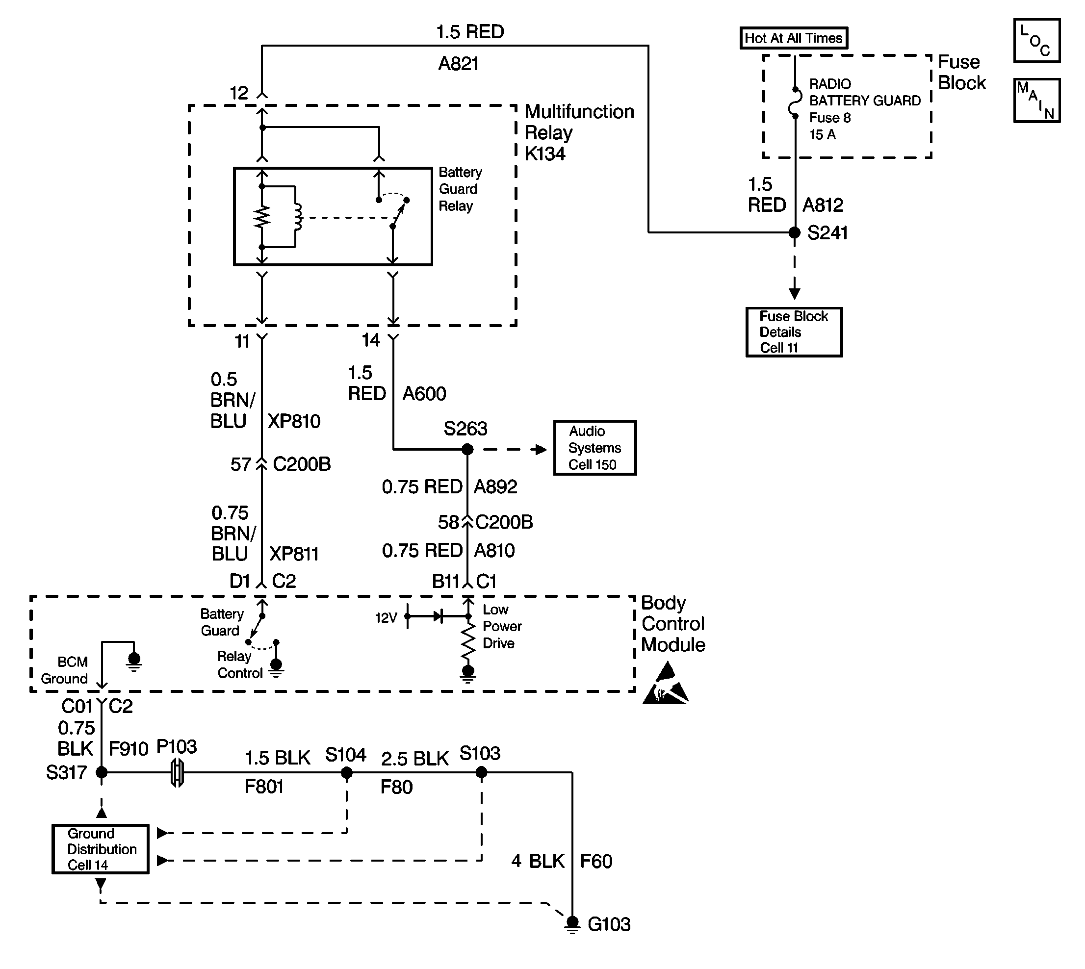
Circuit Description
After the ignition switch is turned to the Lock position, the Body Control Module (BCM) transitions to the High Power Mode (control of the battery guard relay) for 15 minutes and supplies power to the following components:
| • | The Radio Receiver. |
| • | The Radio Interface Module (RIM). |
| • | The Fuel Tank Filler Door Relay coil. |
| • | The Rear Compartment Lid Release Relay coil. |
| • | The Phone (if equipped). |
After the 15 minute time period, the BCM deactivates the High Power Mode and transitions to the Low Power Mode. During the Low Power Mode, the BCM provides memory power to the previous mentioned component. After 3 days of no vehicle activity, the BCM deactivates the output and transitions to the No Controlled Power Mode (the BCM is allowed to go to sleep).
Conditions for Setting the DTC
The BCM monitors the Low Power output every 300 ms at terminal B11. The fault code is set when the BCM commands the Low Power On and the feedback (short to ground) is low for more than 300 ms.
Action Taken When the DTC Sets
| • | The BCM deactivates the Low Power output until the ignition has cycled or the BCM receives a wake-up. |
| • | Stores a DTC B1972 in the BCM memory. |
Conditions for Clearing the DTC
| • | The conditions for the fault are no longer present. |
| • | The use of a scan tool. |
| • | A history DTC will clear after 50 consecutive ignition cycles if the condition for the fault is no longer present. |
Diagnostic Aids
| • | Refer to the relay box end view for terminal assignments when the diagnostics direct you to take electrical measurements at the relay box. The end view is located in Power and Grounding Component Views in Wiring Systems. |
| • | Check the following if the problem is intermittent: |
| - | A damaged wiring harness. Inspect the wiring harness for damage. |
| - | If the wiring harness appears to be in good condition, observe the display on the DMM while moving connectors and wiring harnesses related to the BCM. |
| - | Inspect the wiring harness connectors for backed out terminals, improper mating, improperly formed or damaged terminals, and poor wire terminal to wire connections. |
| • | For additional information, refer to Intermittents and Poor Connections Diagnosis in Wiring Systems. |
Test Description
The following numbers refer to step numbers on the diagnostic table:
-
This test checks for a short to ground. Disconnect all the components from the circuit to get a good reading on the circuit.
-
This test checks which component is pulling the circuit low, indicating an internal failure.
Step | Action | Value(s) | Yes | No |
|---|---|---|---|---|
1 | Was the BCM Diagnostic System Check Performed? | -- | Go BCM Diagnostic System Check | |
Is the measured resistance within the specified value? | OL | |||
Did reconnecting any of these components cause the DMM to indicate continuity to ground? | -- | Go to BCM Diagnostic System Check | ||
4 |
Is the measured resistance within the specified value? | OL | ||
5 | Replace the BCM. Refer to Body Control Module Replacement. Is the replacement complete? | -- | Go to BCM Diagnostic System Check | -- |
6 | Locate and repair the short to ground between the multifunction relay, radio and C200B. Is the repair complete? | -- | Go to BCM Diagnostic System Check | -- |
7 | Locate and repair the short to ground between C200B terminal 58 and BCM connector C1 terminal B11. Is the repair complete? | -- | Go to BCM Diagnostic System Check | -- |
8 | Replace the component that caused the continuity to ground. Is the replacement complete? | -- | Go to BCM Diagnostic System Check | -- |
