Non-DTC Communicating System
| • | Electrical Schematics |
| • | Schematic Reference Table |
| • | Schematic Icon Table |
| • | Component Location Table |
| • | Component Location Views |
| • | Connector End Views |
| • | System Check |
| • | Diagnostic Tables |
| • | Circuit Description |
DTC Communicating System
| • | Electrical Schematics |
| • | Schematic Reference Table |
| • | Schematic Icon Table |
| • | Component Location Table |
| • | Component Location Views |
| • | Connector End Views |
| • | Scan Tool |
| • | Diagnostic Support Information |
Using these elements together will make electrical troubleshooting faster and easier.
Electrical Schematics
The wiring schematic is the cornerstone of electrical diagnosis. Schematics break the entire electrical system down into individual circuits, showing the electrical current paths when a circuit is operating properly. Wiring which is not part of the circuit of interest is referenced to another page, where the circuit is shown complete. Schematics use a top (power) to bottom (ground) sequence to present electrical information.
Important: It is important to realize that no attempt is made on the schematic to represent components and wiring as they physically appear on the vehicle. For example, a 4-foot length of wire is treated no differently in a schematic from one which is only a few inches long.
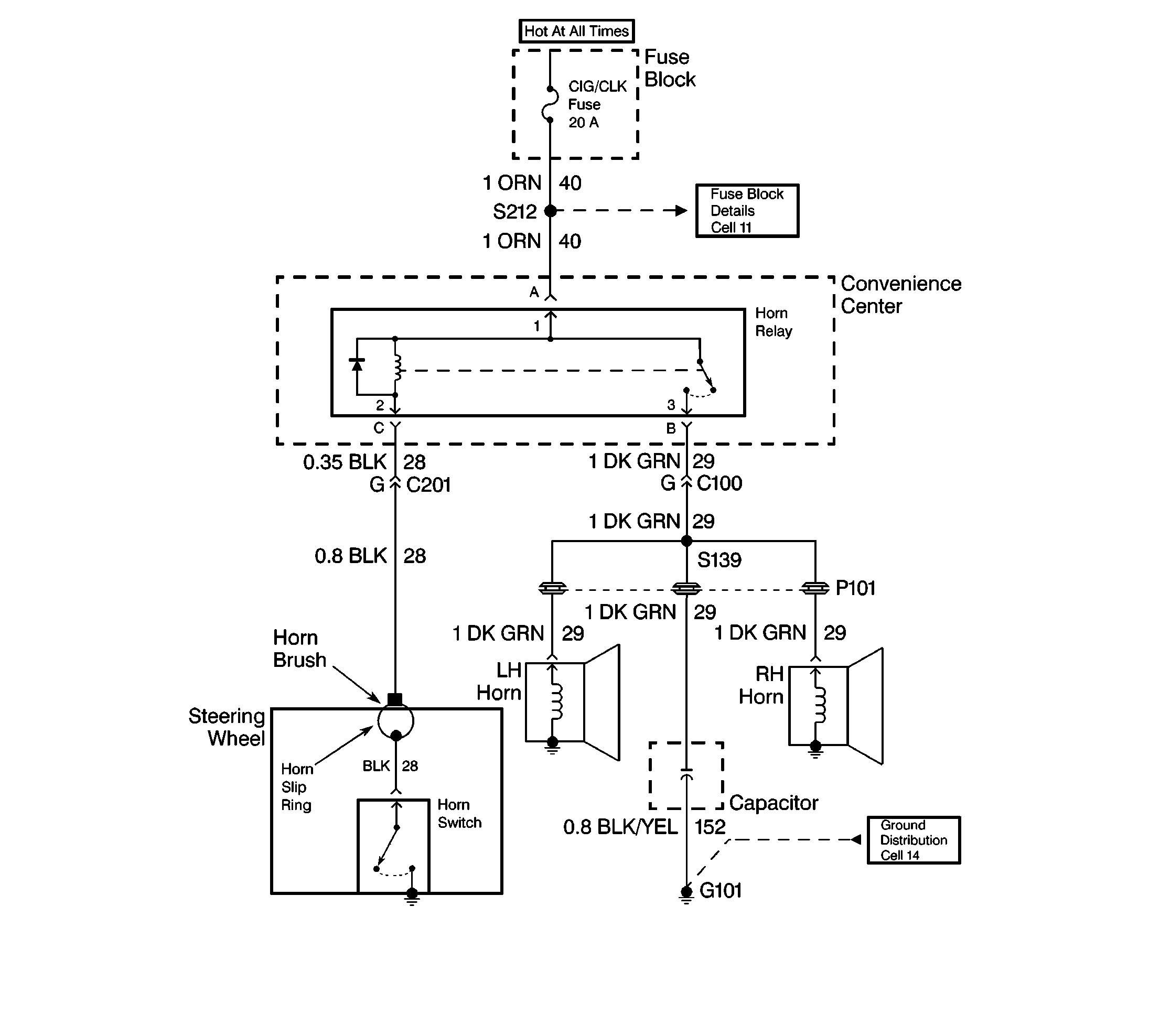
When diagnosing a horn problem, the technician would reference the horn section. The following schematic is a typical example of what would be found in a horn section, along with the included text.

Voltage is applied to the Horn Relay at all times. When the relay coil is grounded by closing the Horn Switch, the relay contacts close. When the relay contacts are closed, both the LH and RH Horns are energized.
Schematic Reference Table
The Schematic Reference Table is used when a circuit is continued into another electrical system's schematic. The Schematic Reference Table will match all references made on schematics to the appropriate service category type number and service category where the schematic's continuation is shown.
Schematic Icon Table
The Schematic Icon Table shows all icons on schematic with their definition or references.
Component Location Table
The Component Location Table helps to find where the components of a system can be located. The table consists of all components, grounds, pass-through grommets and splices that are shown within a system's electrical schematic(s).
The name cells provide the name of the component that is used on the schematic(s). Where connectors are listed, the number of cavities is also provided. This represents the total number of cavities in the connector, regardless of how many are actually used.
The Location cells provide a written location with references to vehicle landmarks. Nearly every component, connector, ground or splice shown on a schematic can be pinpointed visually using Component Location Views illustrations. The Locator View and Connector End View cells include the service category type number and the service category that the view resides in.
Component Location Views
Component Location Views are line illustrations that indicate all of the vehicle's electrical components within each electrical system.
Connector End Views
Connector End Views show the cavity or terminal locations for all the related 2 pin or larger connectors shown in the system schematic(s). The drawings show the connector faces as seen after the harness connector has been disconnected from a component or mating connector. Cavities that are not used are left blank in the table.
In addition, the color and part number of the connector body is provided along with the family/series name.
If you need to backprobe a connector while it is on the component, the order of the terminals must be mentally reversed. The wire color is a help in this situation. If there is more than one wire of the same color, you may need to locate a test point from its terminal number. A useful trick is to imagine that you are probing a terminal from behind the page you are looking at. Then mentally locate that terminal with respect to the keyway or other reference mark.
System Check
The System Check gives a summary of how the system should be operated and what should happen. This is especially important when working on a new system. The System Check will help identify symptoms, lead to diagnosis and confirm normal operation of the system after repair.
Diagnostic Tables
Diagnostic Tables provide a procedure to follow that will locate the condition in a circuit causing a malfunction. If your own knowledge of the system has not produced a quick fix, follow the Diagnostic Table. All procedures are based on symptoms to assist in locating the condition as fast as possible. Diagnostic Tables should exist for all possible (realistic) symptoms and Diagnostic Trouble Codes (DTCs).
Circuit Description
The Circuit Description describes how the circuit works electrically. It details how power, ground, inputs, and signals are supplied to the related components. The Circuit Description also explains the communication and interaction of all components that affect the operation of the system.
Vehicle Zoning
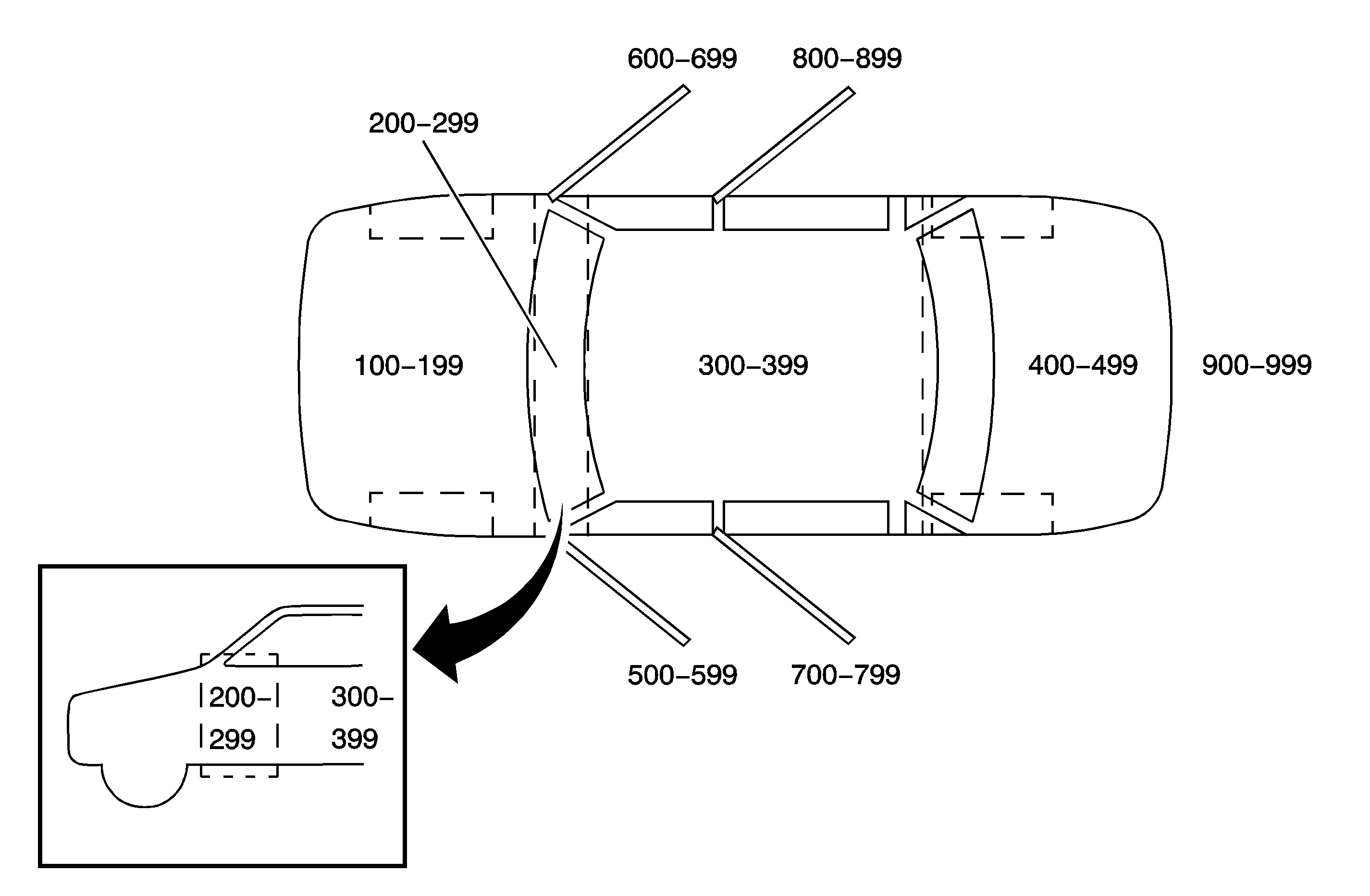
All grounds, in-line connectors, pass-through grommets, and splices are given identifying numbers according to where they are located in the vehicle. The following table explains the numbering system.

Callout Numbers | Zone Description |
|---|---|
100-199 | Engine Compartment (all forward of Dash Panel) |
001-099 * | Additional for Engine Compartment (ONLY used if all 100-199 items are used) |
200-299 | Within Instrument Panel area |
300-399 | Passenger Compartment (From Instrument Panel to the rear wheelhouse) |
400-499 | Luggage Compartment (Rear of the rear wheelhouse |
500-599 | Within Left Front Door |
600-699 | Within Right Front Door |
700-799 | Within Left Rear Door |
800-899 | Within Right Rear Door |
900-999 | Endgate Door (Station Wagon) |
