Removal Procedure
- Raise and support the vehicle. Refer to Lifting and Jacking the Vehicle in General Information.
- Ensure the rear axle support flange fastening bolts remain accessible.
- Remove the tire and wheel assemblies. Refer to Wheel Removal in Tires and Wheels.
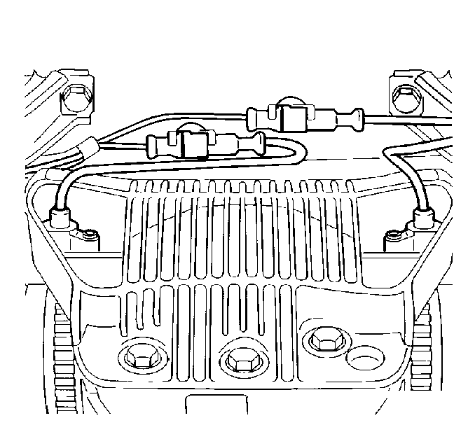
- Remove the rear wheel speed sensor connections.
- Remove the propeller shaft disc joint bolts from the rear differential flange.
- Remove the exhaust system at the rubber body mounts. Refer to Exhaust System Replacement in Exhaust System.
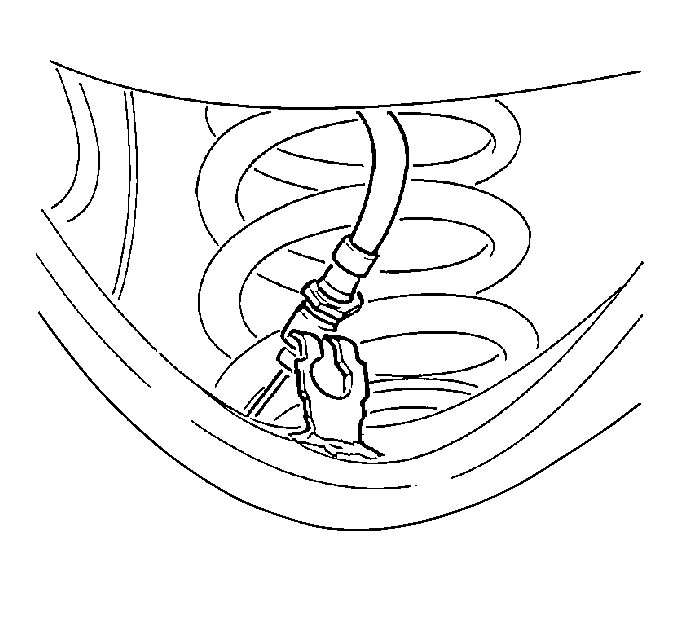
- Remove the brake pipe clips.
- Remove the brake pipes from the lower control arms.
- Remove the parking brake cables from the actuator brackets. Refer to Park Brake Cable Replacement in Parking Brake.
- Remove the rear brake calipers and suspend. Do not open the brake hydraulic system. Refer to Brake Caliper Replacement in Brakes.
- Scribe a reference mark on the vehicle body around the perimeter of the rear axle cradle mount. This will ensure proper positioning during re-installation.
- Support the rear axle cradle.
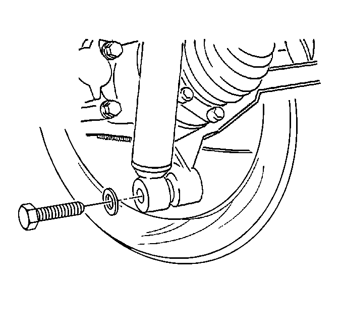
- Remove the shock absorber lower mounting bolts.
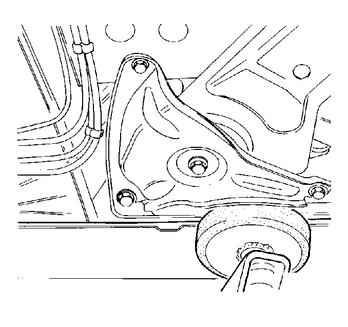
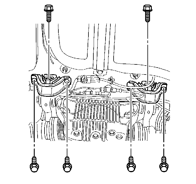
- Remove the rear axle cradle mount bolts.
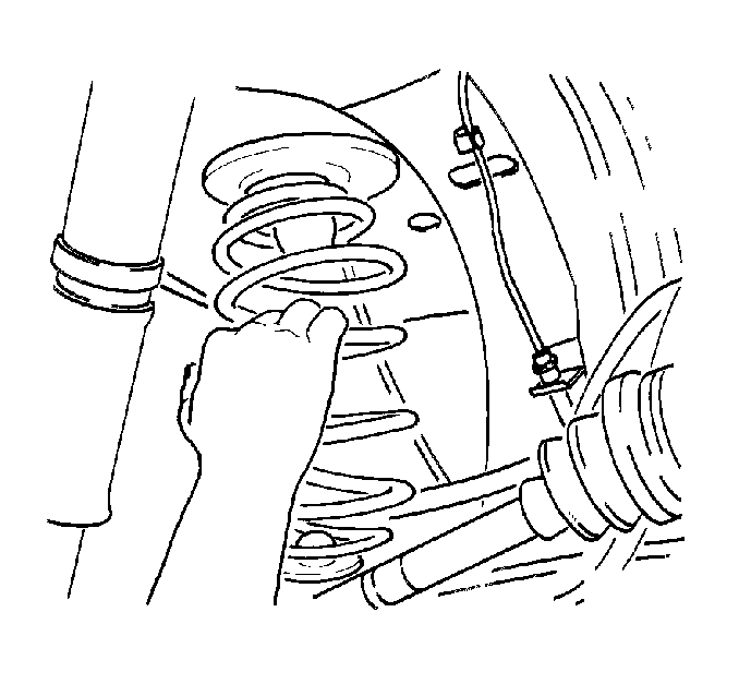
- Pivot the rear axle cradle to allow for removal of the springs.
- Remove the springs.
- Lower the vehicle.
- If not using a universal support table, then support the rear axle cradle with a floor jack and support with stands.
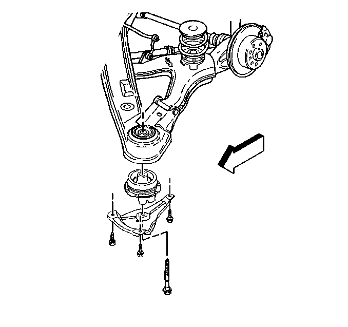
- Remove the rear axle support flange bolts.
- Remove the rear axle support bushing bolts.
- Remove the rear axle cradle.
Important:
• Ensure the rear axle cradle is properly supported to allow for
disproportionate weight distribution. • Support each lower control arm when removing the shock absorber
lower mount bolt.
Installation Procedure
- Perform the following steps to install the rear axle cradle:
- Install the rear axle support bushing bolts.
- Install the rear axle support flange bolts.
- Raise the vehicle.
- Install the springs.
- Align the rear axle cradle to previously scribed marks on the vehicle underbody.
- Install the rear axle cradle mount bolts.
- Support the lower control arm to allow for bolt alignment and for installation.
- Install the shock absorber lower mounting bolts.
- Remove the support from the rear axle cradle.
- Install the rear brake calipers. Refer to Brake Caliper Replacement in Brakes.
- Install the parking brake cables. Refer to Park Brake Cable Replacement in Parking Brake.
- Install the brake pipes to the lower control arms.
- Use the clips to attach the brake pipes to the lower control arms.
- Install the exhaust system to the rubber body mounts. Refer to Exhaust System Replacement in Exhaust System.
- Install the propeller shaft disc joint bolts to the rear differential flange.
- Install the rear wheel speed sensor connections.
- Install the tire and wheel assemblies. Refer to Wheel Installation in Tires and Wheels.
- Lower the vehicle.
- Adjust the rear toe to specifications. Refer to Rear Toe Adjustment in Wheel Alignment.

| 1.1. | Support the rear axle cradle. |
| 1.2. | Place the rear axle cradle into position. |
| 1.3. | Install the rear axle cradle. |
Notice: Use the correct fastener in the correct location. Replacement fasteners must be the correct part number for that application. Fasteners requiring replacement or fasteners requiring the use of thread locking compound or sealant are identified in the service procedure. Do not use paints, lubricants, or corrosion inhibitors on fasteners or fastener joint surfaces unless specified. These coatings affect fastener torque and joint clamping force and may damage the fastener. Use the correct tightening sequence and specifications when installing fasteners in order to avoid damage to parts and systems.
Tighten
Tighten the rear axle support bushing bolts to 125 N·m (92 lb ft).
Tighten
Tighten the rear axle support flange bolts to 65 N·m (48 lb ft).


Tighten
Tighten the rear axle cradle mount bolts to 65 N·m (48 lb ft).

Tighten
Tighten the shock absorber lower mounting bolts to 110 N·m
(81 lb ft).

Tighten
Tighten the propeller shaft disc joint to the rear differential bolts
to 95 N·m (70 lb ft).

