GM Service Manual Online
For 1990-2009 cars only

Fuel Tank

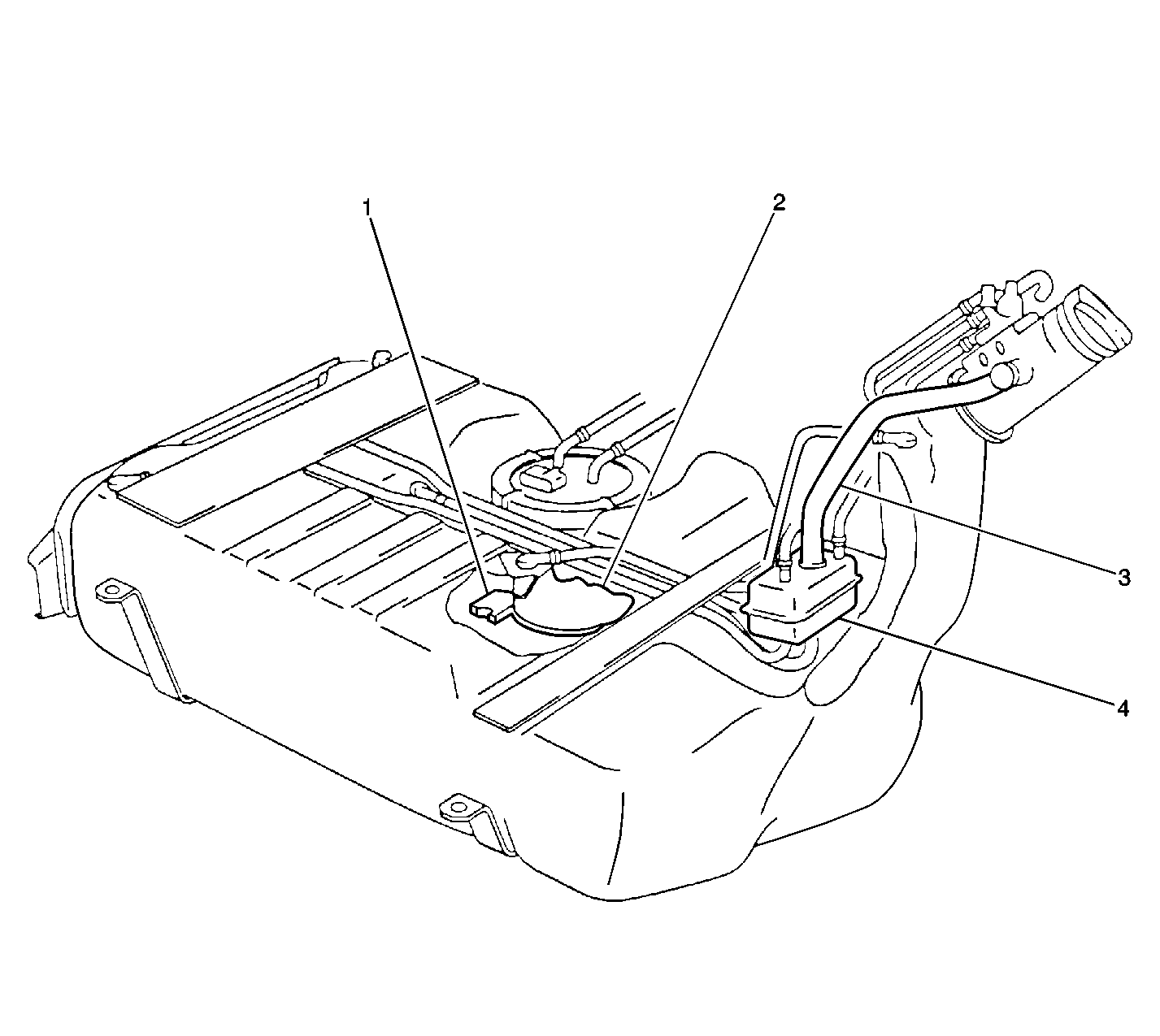
The fuel storage tank is made of high density polyethylene and is located behind the rear wheels. The fuel storage tank is held in place by two metal straps that are attached to the under body of the vehicle. The tank shape includes a sump in order to maintain a constant supply of fuel around the fuel pump strainer during low fuel conditions or during aggressive maneuvers.

The tank also contains a fuel vapor vent valve with a roll-over protection. The vent valve also features a two phase vent calibration which increases the fuel vapor flow to the canister when the operating temperatures increase the tank pressure beyond an established threshold.

Fuel Tank Filler Pipe


Object Number: 20474  Size: LF
(1)The Fuel Level Float (Inside of the Tank)
(2)The Storage Reservoir with the Fuel Pump (Inside the Tank)
(3)The Vent Hose and The Fuel Filler Pipe
(4)The Vent Reservoir and The Fuel Filler Pipe

In order to help prevent any refueling with leaded fuel, the fuel filler pipe has a built-in restrictor and a deflector. The opening in the restrictor will accept only the smaller unleaded gasoline fuel nozzle which must be fully inserted in order to bypass the deflector. The filler pipe is attached to the tank by a section of hose and two hose clamps. The tank is vented during filling by an internal vent tube inside of the filler pipe.

Fuel Filler Cap

Notice: Use a fuel tank filler pipe cap with the same features as the original when a replacement is necessary. Failure to use the correct fuel tank filler pipe cap can result in a serious malfunction of the fuel system.

The fuel tank filler pipe is equipped with a turn to vent screw on the type cap which incorporates a ratchet action in order to prevent over-tightening.

The turn to vent feature allows the fuel tank pressure relief prior to removal. Instructions for proper use are imprinted on the cap cover. A vacuum safety relief valve is incorporated into this cap.

Modular Fuel Sender


Object Number: 20083  Size: SH
(1)The Fuel Pump
(2)The Fuel Gauge Float Arm
(3)The Fuel Reservoir

The modular fuel sender assembly mounts to the threaded opening of the plastic fuel tank with a multi-lipped seal and a threaded retainer (nut). The reservoir, containing the exterior inlet strainer, the electric fuel pump and the pump strainer, maintains contact with the tank bottom. This design provides:

    • Optimum fuel level in the integral fuel reservoir during all fuel tank levels and during driving conditions
    • An improved tank fuel level measuring accuracy
    • An improved coarse straining and added pump inlet filtering
    • More extensive internal fuel pump isolation for noiseless operation

The modular fuel sender assembly maintains an optimum fuel level in the reservoir (bucket). The fuel entering the reservoir is drawn in by the following components:

    • The first stage of the fuel pump through the external strainer
        and/or
    • The secondary umbrella valve
        or
    • The return fuel line, whenever the level of fuel is below the top of the reservoir

Fuel Pump

The electric fuel pump is a turbine pump which is located inside of the modular fuel sender. The electric fuel pump operation is controlled by the ECM through the fuel pump relay.

Fuel Sender Strainers

The strainers act as a coarse filter to perform the following functions:

    • Filter contaminants
    • Separate water from fuel
    • Provide a wicking action that helps draw fuel into the fuel pump

Fuel stoppage at the strainer indicates that the fuel tank contains an abnormal amount of sediment or water. Therefore, the fuel tank will need to be removed and cleaned, and the filter strainer should be replaced. Refer to Fuel System Cleaning .

In-Line Fuel Filter

A steel in-line filter is used in the fuel feed line near the fuel tank. The filter element is made of paper, and is designed to trap particles in the fuel that may damage the injection system.

Fuel and EVAP Lines -- Nylon Fuel Lines

Caution: In order to reduce the risk of fire and personal injury observe the following items:

   • Replace all nylon fuel pipes that are nicked, scratched or damaged during installation, do not attempt to repair the sections of the nylon fuel pipes
   • Do not hammer directly on the fuel harness body clips when installing new fuel pipes. Damage to the nylon pipes may result in a fuel leak.
   • Always cover nylon vapor pipes with a wet towel before using a torch near them. Also, never expose the vehicle to temperatures higher than 115°C (239°F) for more than one hour, or more than 90°C (194°F) for any extended period.
   • Apply a few drops of clean engine oil to the male pipe ends before connecting fuel pipe fittings. This will ensure proper reconnection and prevent a possible fuel leak. (During normal operation, the O-rings located in the female connector will swell and may prevent proper reconnection if not lubricated.)


Object Number: 60884  Size: SH
(1)The Fuel Feed Line
(2)The Fuel Tank
(3)The Fuel Filter
(4)The EVAP Vapor Line
(5)The Fuel Return Line
(6)The EVAP Vapor Line
(7)The Right Rear Axle Shaft

Object Number: 60866  Size: SH
(1)Quick Connect Fittings
(2)The Level Control Line
(3)The EVAP Vapor Line
(4)The Fuel Return Line
(5)The Fuel Supply Line

Object Number: 60907  Size: SH
(1)The Right Front Brake Rotor
(2)The EVAP Vent Line
(3)The Fuel Return Line
(4)The EVAP Purge Line
(5)The Fuel Supply Line
(6)The Level Control Air Line
(7)The Frame Rail
(8)The Rear of the Wheel Well
(9)The EVAP Vapor Line
(10)The Canister

The nylon fuel lines are designed to perform the same function as the steel or rubber fuel lines. The nylon lines are constructed to withstand the maximum fuel system pressure, exposure to any fuel additives, and changes in temperature.

The fuel feed, the return, the vacuum and the EVAP lines are assembled as a harness. The retaining clips hold the lines together and provide a means for attaching the lines to the vehicle. The sections of the lines that are exposed to any chafing, high temperature or vibration are protected with a heat resistant rubber hose and/or a co-extruded conduit.

The nylon fuel lines are somewhat flexible and can be formed around gradual turns under the vehicle. However, if the nylon lines are forced into sharp bends, nylon lines will kink and restrict the fuel flow. Also, once the fuel lines are exposed to fuel, the fuel lines may become stiffer and more likely to kink if bent too far. Take special care when working on a vehicle with any nylon fuel lines.

EVAP Lines and Hoses


Object Number: 21580  Size: SH
(1)The Fuel Return
(2)The Fuel Feed

The EVAP line extends from the fuel tank vent valve to the EVAP canister and into the engine compartment. The EVAP line is made of nylon and connects to the EVAP canister with a fuel resistant rubber hose and quick connect fittings.

Fuel Pressure Regulator

The fuel pressure regulator is a diaphragm operated relief valve having the fuel pump pressure on one side and the regulator spring pressure and the intake manifold vacuum on the other side. The function of the fuel pressure regulator is to maintain approximately 350 kPa across the director spray plate under all of the operating conditions. The pressure regulator compensates for the engine load by increasing the fuel pressure as the engine intake manifold vacuum drops. The pressure regulator is mounted on the fuel rail.

With the engine running at idle, the system fuel pressure at the pressure test connection should be 317-407 kPa (46-59 psi). If the pressure regulator supplies a fuel pressure which is too low or too high, a driveability condition will result.
Fuel Rail


Object Number: 61654  Size: SH
(1)The Fuel Rail
(2)The Fuel Supply Line
(3)The Fuel Return Line
(4)The Fuel Pressure Regulator

The fuel rail consists of four parts:

    • The pipe that carries fuel to each injector
    • The fuel pressure regulator
    • The fuel pressure test port
    • Six individual fuel injectors

The fuel rail is mounted on the intake manifold and distributes the fuel to each cylinder through the individual injectors.

The fuel is delivered from the pump through the fuel feed line to the inlet port of the fuel rail pipe. From the fuel feed inlet, fuel is directed to the rail pipe to the fuel pressure regulator. Any fuel in excess of the injector needs flows back through the pressure regulator assembly to the outlet port of the fuel rail. The fuel then flows through the fuel return line to the fuel tank to begin the cycle again.

Fuel Injectors

The fuel injector is a solenoid device that is controlled by the ECM that meters the pressurized fuel to a single cylinder. When the ECM energizes the injector coil, a normally closed ball valve opens, allowing the fuel to flow past a director plate to the injector outlet. The director plate has holes that control the fuel flow, generating a dual conical spray pattern of finely atomized fuel at the injector outlet. The fuel from the outlet is directed at both of the intake valves, causing the fuel to become further vaporized before entering the combustion chamber.

The fuel injectors will cause various driveability conditions if the following conditions occur:

    • If the injectors will not open
    • If the injectors are stuck open
    • If the injectors are leaking
    • If the injectors have a low coil resistance

Throttle Body


Object Number: 21407  Size: SH
(1)O-Ring Seals

The throttle body contains a dual throttle valve which controls the amount of air that is being delivered to the engine. A coolant passage under the throttle valve heats the throttle body.

The Throttle Position (TP) sensor is mounted on the throttle body. The TP sensor and the minimum air stop are not adjustable.

Idle Air Control (IAC) Valve


Object Number: 60902  Size: SH

The purpose of the Idle Air Control (IAC) Valve is to control the engine idle speed. The throttle blade, when closed, allows a small amount of air into the intake manifold. The IAC system controls the idle speed by allowing a controlled amount of air to bypass the throttle blade via a passage in the IAC valve. The IAC valve consists of a rotating shutter that is held in a neutral position by the opposing springs within the valve assembly (which is equal to a slightly elevated idle). The switched B+ is provided to the drive unit within the IAC valve. The ECM controls the valve via two control circuits, one control circuit is used in order to drive the valve open and the other control circuit is used in order to drive the valve closed. The ECM Pulse Width Modulates both of the control circuits simultaneously. The ratio of the frequency between the two PWM signals determines the direction and the amount that the drive unit rotates the shutter within the valve. As the shutter closes, the bypass air flow is reduced and the idle speed decreases. The ECM commands the shutter open, allowing more air to bypass the throttle plates in order to increase the idle speed.

Fuel Pump Relay

The fuel pump relay allows the ECM to energize the fuel pump. The ECM enables the fuel pump whenever the CKP sensor pulses are detected.

Engine Control Module (ECM), Inputs/Sensors

The ECM receives the data from various information sensors and other inputs. For detailed information on the ECM, the sensors and the other inputs, Refer to Engine Controls, Engine Control Module (ECM), Inputs/Sensors.

Accelerator Controls

The accelerator control system is a cable type. There are no linkage adjustments. Therefore, you must use the specific cable for each application.

When the work has been performed on the accelerator controls, always make sure that all of the components are installed correctly and that the linkage and the cables are not rubbing or binding in any manner. The throttle should operate freely without a bind between a full closed and a wide open throttle.