Knock Sensor Replacement Bank 1
Removal Procedure
- Disconnect the ground cable from the battery.
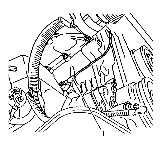
- Disconnect the wiring harness from the knock sensor (1).
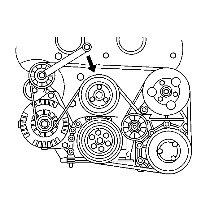
- Release the accessory drive belt by moving the belt tension roller in the direction of the arrow (clockwise).
- Remove the accessory drive belt from the belt tension roller.
- Remove the fastening bolts from the belt tension roller and remove the tension roller.
- Remove the cable for the knock sensor from the retaining clips on the rear timing belt cover.
- Remove the lower air dam on the lower engine cover for access to the alternator.
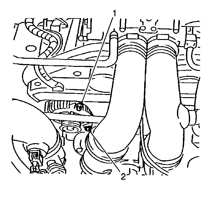
- Remove the upper alternator fastening bolt (1). Loosen the lower alternator fastening bolt.
- Remove the air cooling duct from the alternator.
- Swing the alternator aside. Observe the cable routing for the knock sensor.
- Remove the knock sensor from the engine block.
Caution: Unless directed otherwise, the ignition and start switch must be in the OFF or LOCK position, and all electrical loads must be OFF before servicing any electrical component. Disconnect the negative battery cable to prevent an electrical spark should a tool or equipment come in contact with an exposed electrical terminal. Failure to follow these precautions may result in personal injury and/or damage to the vehicle or its components.
Important:
• There is a bracket for a cable bundle on the lower fastening bolt. • The cable for the knock sensor is guided past the rear timing
belt cover by several retaining clips. Only one retainer clip is shown.
Installation Procedure
- Thoroughly clean the mating surfaces of the knock sensor and the engine block. The entire contact surface of the knock sensor must lie directly on the engine block.
- Install the knock sensor (1) into the engine block.
- Install the cable for the knock sensor into the retaining clips. Ensure that the cable does not contact any moving parts.
- Connect the wiring harness for the knock sensor.
- Swing the alternator back into position. The cable for the knock sensor runs between the engine block and the alternator.
- Install the air cooling duct onto the alternator.
- Install/tighten the upper alternator fastening bolt (1) and the lower alternator fastening bolt (2).
- Install the belt tension roller to the cylinder head. The cable for the knock sensor runs between the cylinder head and the belt tension roller bracket.
- Install the belt tension roller fastening bolts. Install the bracket for the cable bundle at the lower fastening bolt.
- Rotate the belt tension roller in the direction of the arrow (clockwise).
- Install the accessory drive belt. Release the belt tension roller.
- Install the air dam to the underside of the vehicle.

Important: Do not use washers, spring washers, or toothed washers when installing the knock sensor. Tighten all of the fasteners to the proper torque.
Tighten
Tighten the sensor to 22 N·m (16 lb ft).
Important: The cable for the knock sensor is guided past the rear timing belt cover by several retaining clips. Only one retainer clip is shown.


Important: Make sure that the accessory drive belt routing and running direction are correct.
The accessory drive belt tension is automatically adjusted by the tension roller.
Knock Sensor Replacement Bank 2
Removal Procedure
- Remove the resonance chamber.
- Remove the cable from the retaining clips.
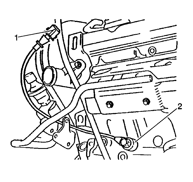
- Disconnect the wiring harness (1) from the knock sensor (2).
- Securely attach a scrap piece of wire about 36 inches long to the knock sensor pigtail. Later, this will be used as a pull wire to guide the new sensor pigtail back through the same routing.
- Loosen the three fastening bolts from the power steering pump pulley to the power steering pump.
- Mark the running direction of the accessory drive belt.
- Release the accessory drive belt by moving the belt tension roller in the direction of the arrow (clockwise), and remove the belt.
- Remove the power steering pump pulley.
- If present, remove the lower engine compartment cover, and the fastening bolts for the front left vibration damper from the front axle body bracket.
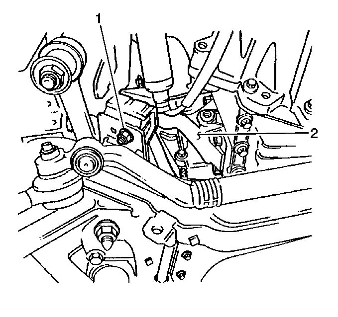
- Remove the lower nut (1) from the engine damping block.
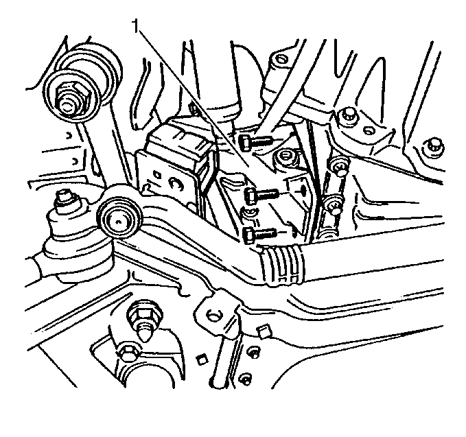
- Loosen the four fastening bolts for the engine bracket (1) a few turns.
- Using a hydraulic jack and a suitable adaptor, lift the transmission carefully until the pin comes out of the bracket.
- Remove all 4 fastening bolts (1) for the engine bracket.
- Remove the engine bracket with the engine damping block.
- Remove the knock sensor cable. Observe the cable routing. Gently pull the knock sensor pigtail through the wiring conduit and out. Stop when the pull wire is free of the conduit at both ends.
- Detach the knock sensor from the pull wire, leaving the pull wire in place.

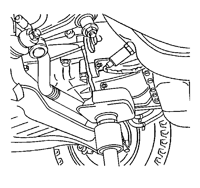
Notice: Do not jack up the transmission by the pan. Use a suitable lifting point in order to prevent damage to the components.

Installation Procedure
- Thoroughly clean the mating surfaces of the knock sensor and the engine block. The entire contact surface of the knock sensor must lie directly on the engine block.
- Install the knock sensor (2) to the engine block.
- Securely fasten the knock sensor pigtail to the pull wire that was left in place during the removal procedure.
- Use the pull wire in order to guide the knock sensor pigtail back through the proper route, out to the retaining clip at the power steering pump.
- Remove the pull wire.
- Connect the wiring harness (1) to the knock sensor.
- Fasten the harness to the retaining clips.
- Install the pulley onto the power steering pump. Then, tighten the fastening bolts.
- Rotate the belt tension roller in the direction of the arrow (clockwise).
- Install the accessory drive belt. Release the belt tension roller.
- Install the resonance chamber.
- Loosen the upper fastening nut for the engine damping block until the engine damping block can be moved in the engine bracket.
- Install the engine bracket (1) with the engine damping block. Install/tighten the 4 fastening bolts.
- Lower the transmission carefully until the guide pin and the fastening stud sit correctly in the front axle body bracket.
- Install/tighten the lower fastening nut (1) for the engine damping block.
- Install/tighten the fastening bolts for the front left vibration damper.
- Install the lower engine compartment cover, if so equipped.

Important: Do not use any washers, any spring washers, or any toothed washers when installing the Knock Sensor. Tighten all of the fasteners to the proper torque.
Tighten
Tighten the sensor to 22 N·m (16 lb ft).
Important: When routing the cable for the knock sensor, ensure that the cable does not contact the exhaust manifold or any moving parts (e.g. accessory drive belt).

Important: Make sure that the accessory drive belt routing and running direction are correct.
The accessory drive belt tension is automatically adjusted by the tension roller.


