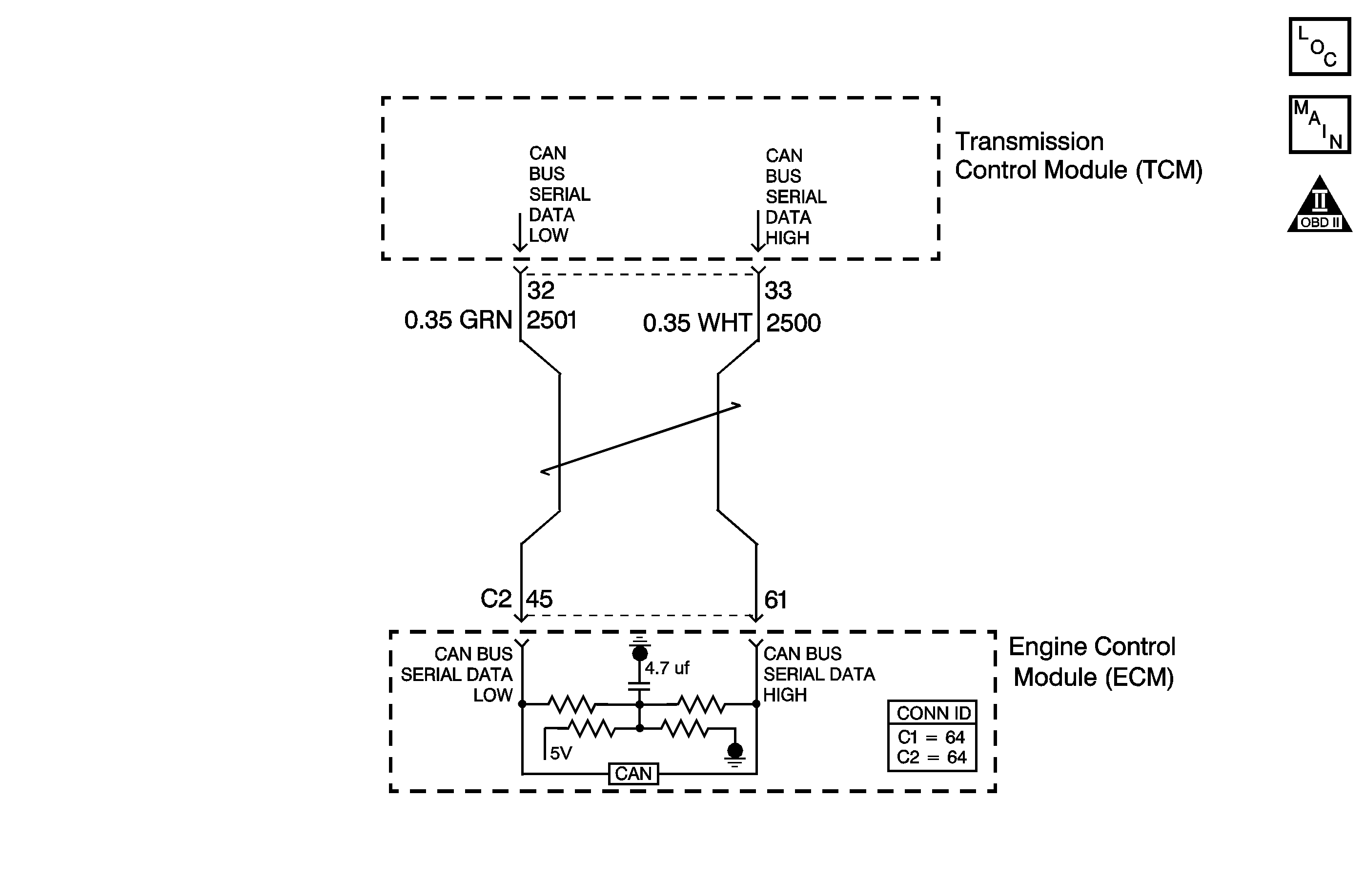
Circuit Description
The controller area network (CAN) consists of two separate conductors between the ECM and the transmission control module (TCM). Each module sends information by toggling the circuits high or low to produce pulse width signals, which the other modules decode.
The CAN data stream contains information such as status messages for relevant operating parameters, device requests and acknowledgments, and state-of-health messages.
When the TCM has not received ECM data for a specified amount of time, then DTC U2105 will set. DTC U2105 is a type B DTC.
Conditions for Running the DTC
The ignition is ON.
Conditions for Setting the DTC
The TCM has not received ECM messaging for 40 milliseconds.
Action Taken When the DTC Sets
| • | The TCM requests the ECM to illuminate the malfunction indicator lamp (MIL) during the second consecutive drive trip in which the Conditions for Setting the DTC are met. |
| • | The TCM turns off power to all solenoids. When the solenoids are off: |
| - | The transmission will operate in fifth gear if the vehicle has successfully completed a 1-2 upshift in the current ignition cycle. If the vehicle has not completed a 1-2 upshift in the current ignition cycle, the transmission will operate in fourth gear. If the transmission is operating in fifth gear, fourth gear may be obtained if the engine is stopped briefly and started again. |
| - | The line pressure is at maximum, and updates to the transmission adaptive pressure (TAP) memory cells are discontinued. |
| • | Torque management is inhibited. |
| • | At the time of the first failure, the TCM records the operating conditions when the Conditions for Setting the DTC are met. The TCM stores this information as a Failure Record. |
| • | At the time of the second failure, the ECM records the operating conditions when the Conditions for Setting the DTC are met. The ECM stores this information as a Freeze Frame. |
| • | The TCM stores DTC U2105 in TCM history. |
Conditions for Clearing the MIL/DTC
| • | The ECM turns OFF the MIL after the sixth consecutive drive trip in which the TCM does not send a MIL illumination request. |
| • | A scan tool can clear the MIL/DTC. |
| • | The TCM clears the DTC from TCM history if the vehicle completes 40 warm-up cycles without an emission related diagnostic fault occurring. |
| • | The TCM cancels the default actions when the ignition is OFF long enough in order to power down the TCM. |
Diagnostic Aids
This DTC sets when a communication fault exists between the ECM and the TCM. Inspect for DTCs U 2100, U 2104 and U 2106. If any of these DTCs are present, diagnose them first.
Test Description
The number below refers to the step number on the diagnostic table.
Step | Action | Value(s) | Yes | No | ||||||||||||||||
|---|---|---|---|---|---|---|---|---|---|---|---|---|---|---|---|---|---|---|---|---|
1 | Did you perform the Diagnostic System Check - Engine Controls? | -- | Go to Step 2 | Go to Diagnostic System Check - Engine Controls in Engine Controls - 2.6L and 3.2L | ||||||||||||||||
Important:
Did DTC U2105 reset? | -- | Go to Step 3 | Go to Intermittent Conditions in Engine Controls - 2.6L and 3.2L | |||||||||||||||||
3 | Did you record a Failure record for any ECM DTCs? | -- | Go to the applicable ECM DTC | Go to Step 4 | ||||||||||||||||
4 | Test the CAN serial data low circuit (CKT 2501) and the CAN serial data high circuit (CKT 2500) between the TCM and the ECM for the following conditions:
Did you find a condition? | -- | Go to Step 5 | Go to Step 6 | ||||||||||||||||
5 | Repair the wiring as necessary. Refer to Wiring Repairs in Wiring Systems. Is the action complete? | -- | Go to Step 7 | -- | ||||||||||||||||
6 | Replace the ECM. Refer to Engine Control Module Replacement . Is the action complete? | -- | Go to Step 7 | -- | ||||||||||||||||
7 | Perform the following procedure in order to verify the repair:
Has the test run and passed? | -- | Go to Step 8 | Go to Step 2 | ||||||||||||||||
8 | With the scan tool, observe the stored information, capture info and DTC info. Does the scan tool display any DTCs that you have not diagnosed? | -- | Go to Diagnostic Trouble Code (DTC) List in Engine Controls - 2.6L and 3.2L | System OK |
