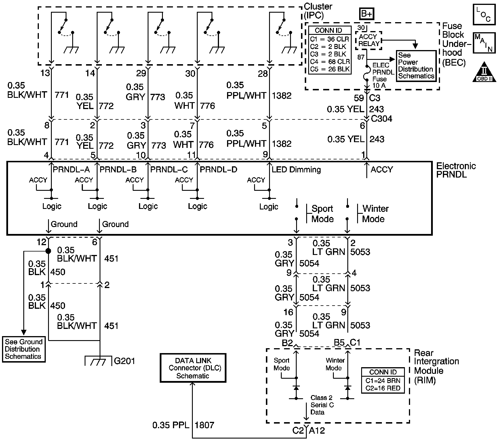
Circuit Description
The sport and economy shift modes allow driver selection of two different shift patterns. Sport mode programming in the transmission control module (TCM) increases transmission line pressure and extends shift points for performance enhanced driving. In the economy mode, the TCM uses standard programming, permitting normal line pressure and shifting. The sport mode switch is a console mounted momentary contact switch located on the electronic PRNDL assembly. Accessory voltage is supplied to the electronic PRNDL assembly through the ELEC PRNDL fuse. When the sport mode switch is depressed, it momentarily contacts the switch signal circuit. The rear integration module (RIM) recognizes the voltage on the circuit and sends a class 2 serial data message to the dash integration module (DIM). The DIM sends a class 2 message to the engine control module (ECM). The ECM sends a request to the transmission control module (TCM) through the controller area network (CAN) to enable the sport mode program.
The TCM evaluates the request, and if operating conditions are correct for enabling the program, the TCM sends a confirmation message to the ECM. The ECM then requests the instrument panel cluster (IPC) to illuminate the sport mode indicator.
The sport mode feature remains enabled until the sport mode switch is pressed again. Once disabled, the TCM will return to the economy mode programming.
Diagnostic Aids
| • | Test the instrument panel cluster (IPC) for proper operation and lamp illumination. Refer to Diagnostic System Check - Instrument Cluster in Instrument Panel, Gages, and Console. |
| • | Test the rear integration module (RIM) for proper sport mode switch input and output operation. Refer to Body Control System Description and Operation in Body Control System. |
Test Description
The numbers below refer to the step numbers on the diagnostic table.
-
Diagnose all communication and body DTCs first. The DTC may be the source of the symptom.
-
No PRNDL display could be open in the electronic PRNDL assembly accessory circuit.
-
This step tests the sport mode circuit by bypassing the electronic PRNDL assembly.
Step | Action | Value(s) | Yes | No | ||||||||||||||
|---|---|---|---|---|---|---|---|---|---|---|---|---|---|---|---|---|---|---|
Does the scan tool display DTCs that start with "U" or "B"? | -- | Go to Diagnostic Trouble Code (DTC) List in Body Control System | Go to Step 2 | |||||||||||||||
2 |
Does the sport mode indicator illuminate On and Off with switch operation? | -- | Go to Intermittent Conditions in Engine Controls - 2.6L and 3.2L | Go to Step 3 | ||||||||||||||
3 | Is the sport mode indicator always On? | -- | Go to Step 9 | Go to Step 4 | ||||||||||||||
Move the gear selector from Park through all gear positions while observing the electronic PRNDL display. Does the PRNDL display all gear positions? | -- | Go to Step 6 | Go to Step 5 | |||||||||||||||
5 | Test the accessory voltage circuit (CKT 243) for an open. Refer to Testing for Continuity in Wiring Systems. Did you find and correct the condition? | -- | Go to Step 12 | Go to Step 7 | ||||||||||||||
Is the sport mode indicator illuminated? | -- | Go to Step 11 | Go to Step 7 | |||||||||||||||
7 | Test the electronic PRNDL ground circuits (CKT 450 and 451) for an open. Refer to Testing for Continuity in Wiring Systems. Did you find and correct the condition? | -- | Go to Step 12 | Go to Diagnostic Starting Point - Body Control System in Body Control System | ||||||||||||||
8 | Test the sport mode switch signal circuit (CKT 5054) for an open. Refer to Testing for Continuity in Wiring Systems. Did you find and correct the condition? | -- | Go to Step 12 | Go to Step 9 | ||||||||||||||
9 | Test the sport mode switch signal circuit (CKT 5054) for a short to ground. Refer to Testing for Short to Ground in Wiring Systems. Did you find and correct the condition? | -- | Go to Step 12 | Go to Step 10 | ||||||||||||||
10 | While observing the sport mode indicator on the IPC, disconnect the electronic PRNDL assembly from the console wiring harness connector. Is the IPC sport mode indicator no longer illuminated? | -- | Go to Step 11 | Go to Diagnostic Starting Point - Body Control System in Body Control System | ||||||||||||||
11 | Replace the electronic PRNDL assembly. Refer to Front Floor Console Replacement in Instrument Panel, Gages, and Console. Is the action complete? | -- | Go to Step 12 | -- | ||||||||||||||
12 | After repairs, test the sport/economy mode under the following conditions:
Does the sport/economy mode operate as described? | -- | System OK | Go to Step 1 |
