For 1990-2009 cars only
Removal Procedure
- Relieve the fuel system pressure. Refer to Fuel Pressure Relief .
- Refer to Metal Collar Quick Connect Fitting Service in order to disconnect the following quick connect fittings from the fuel rail.
- Disconnect the evaporative emission (EVAP) quick connect fitting (3). Refer to Plastic Collar Quick Connect Fitting Service .
- Open the retainer (4) located at the engine control module (ECM) bracket in order to remove the chassis hose/pipes.
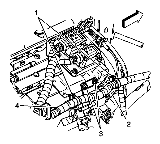
- Disconnect the 2 cable harness clips (1) securing the engine wiring harness (4) to the ECM bracket (2).
- Remove the 2 bolts (3) securing the afterboil coolant pump to the ECM bracket, and position aside.
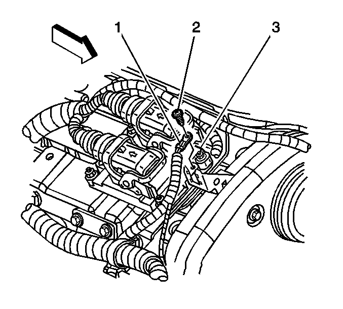
- Remove the screw (2) securing the ECM ground wire (1) to the ECM (3).
- Flip the release levers to the open position (3) and disconnect the ECM connectors (2) from the ECM (5).
- Remove the bolt securing the coolant inlet pipe to the ECM bracket.
- Remove the ECM bracket bolts from the following:
- Remove the ECM bracket from the engine with the ECM still attached, and position aside.
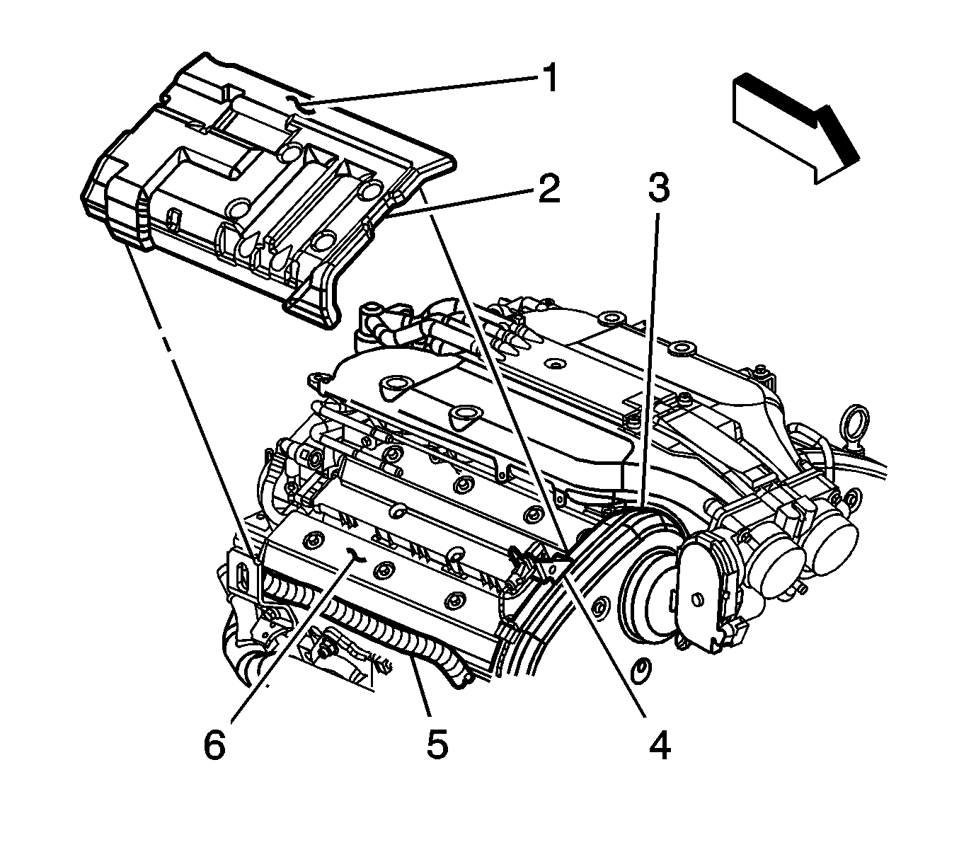
- Remove the right cover (1) from the cam cover (6).
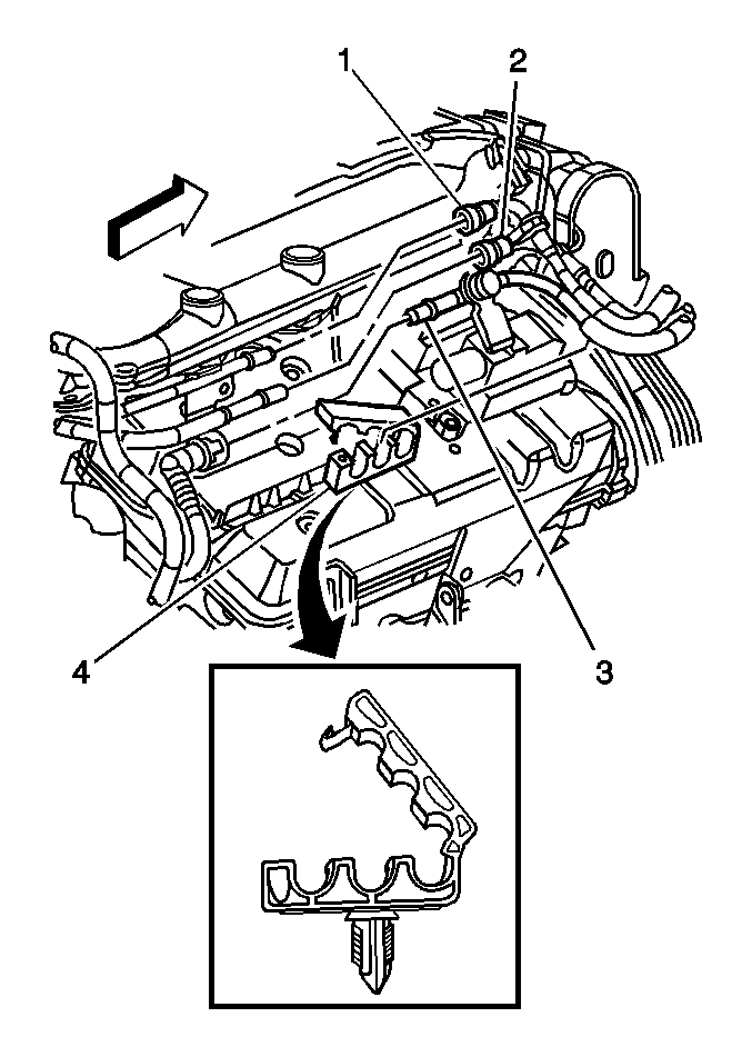
| • | The return hose/pipe (1) |
| • | The feed hose/pipe (2) |
| • | Plug the open outlets to prevent fluid loss and contamination. |
Notice: Always turn the ignition off when installing or removing the ECM connectors in order to prevent damage to the components.
Important: Ensure the ignition is in the OFF position.
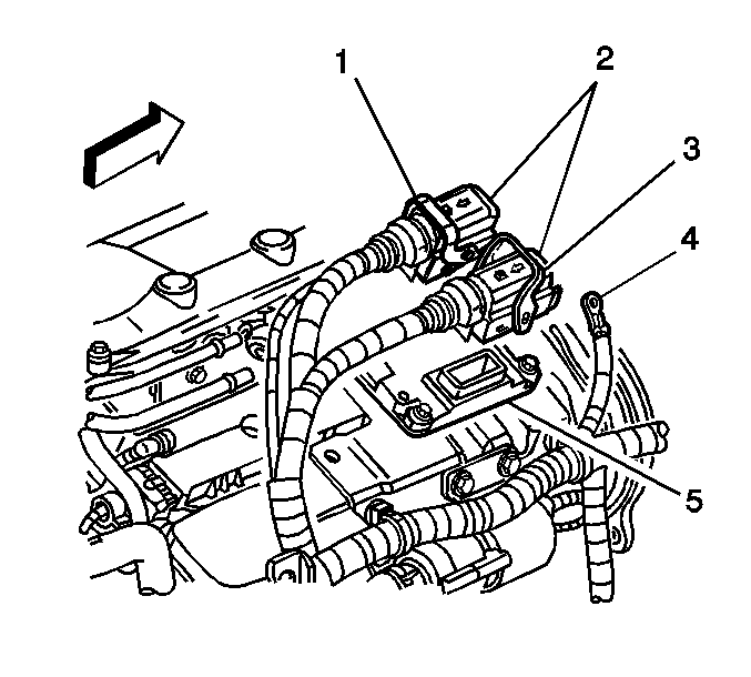
Notice: In order to prevent any possible electrostatic discharge damage to the ECM, do not touch the connector pins.
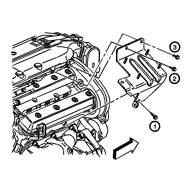
| • | The intake plenum |
| • | The cylinder head |
Installation Procedure
- Fully seat the right cover (1) to the cam cover (6), aligning the following:
- Position the ECM and bracket to the engine.
- Install the ECM bracket bolts to the following:
- Tighten the ECM bracket bolts in the sequence shown.
- Install the bolt securing the coolant inlet pipe to the ECM bracket.
- Carefully align the harness connectors (2) with the ECM connectors.
- Guide the connectors (2) into place while moving the release levers to the locked position (1).
- Install the screw (2) securing the ECM ground wire (1) to the ECM (3).
- Install the 2 bolts (3) securing the afterboil coolant pump to the ECM bracket.
- Connect the 2 cable harness clips (1) securing the engine wiring harness (4) to the ECM bracket (2).
- Insert the chassis hose/pipes into the retainer (4) located at the ECM bracket.
- Close the retainer (4).
- Connect the EVAP quick connect fitting (3). Refer to Plastic Collar Quick Connect Fitting Service .
- Refer to Metal Collar Quick Connect Fitting Service in order to connect the following quick connect fittings to the fuel rail.

| • | Insert the cover (1) between the engine wiring harness (5) and the cam cover (6). |
| • | The front notch (2) of the cover (1) with the right knock sensor bracket (4). |
| • | Position the cover (1) forward against the engine rear timing belt cover (3). |
| • | Locate the cover (1) between the intake manifold and the cam cover bolt heads. |

| • | The cylinder head |
| • | The intake plenum |
Notice: Refer to Fastener Notice in the Preface section.
Tighten
| • | Tighten the ECM bracket to cylinder head bolt to 20 N·m (15 lb ft). |
| • | Tighten the ECM bracket to intake plenum bolts to 8 N·m (71 lb in). |
Tighten
Tighten the coolant inlet pipe support bolt to 20 N·m (15 lb ft).


Tighten
Tighten the ECM ground wire screw to 4.5 N·m
(40 lb in).

Tighten
Tighten the afterboil coolant pump bolts to 10 N·m
(89 lb in).

| • | The feed hose/pipe (2) |
| • | The return hose/pipe (1) |
