For 1990-2009 cars only
Throttle Body Heater Inlet Hose/Pipe Replacement LA3, LY9
Removal Procedure
- Partially drain the cooling system. Refer to Cooling System Draining and Filling .
- Disconnect the following from the remote power steering fluid reservoir (1):
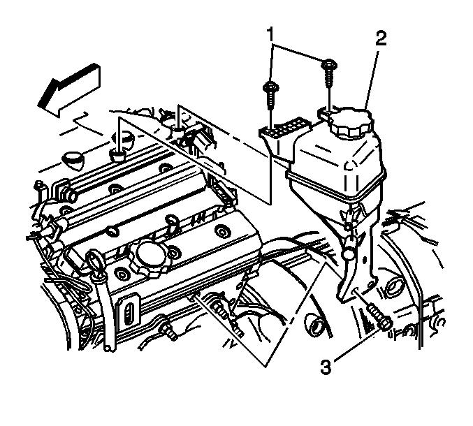
- Remove the remote power steering fluid reservoir mounting bolts (1, 3) ONLY, and position aside.
- Remove the wiper motor module in order to gain access to the rear of the throttle body heater inlet hose. Refer to Windshield Wiper System Module Replacement in Wipers/Washer Systems.
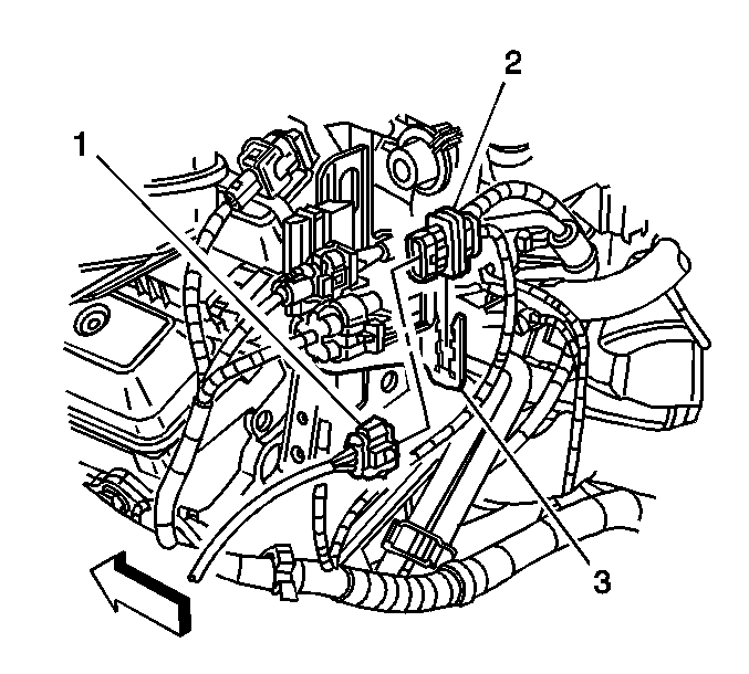
- Disconnect the heated oxygen sensor connector (2) from the rear of the throttle body heater inlet hose/pipe (3).
- Disconnect the throttle body heater inlet hose from the water crossover, using 90° needlenose pliers.
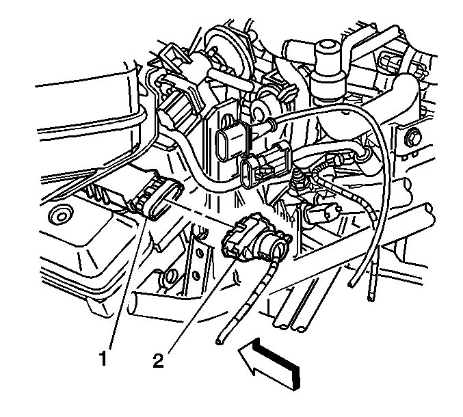
- Disconnect the electrical connector (2) from the coil pack (1).
- Disconnect the following from the front of the throttle body heater inlet hose/pipe:
- Disconnect the vacuum brake booster hose (3) from the vacuum source.
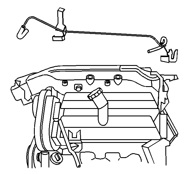
- Remove the bolts securing the throttle body heater inlet hose/pipe to the following:
- Disconnect the throttle body heater inlet hose from the throttle body.
- Remove the throttle body heater inlet hose/pipe from the engine.
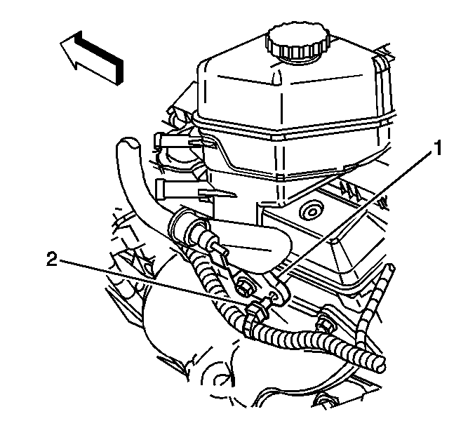
| • | The brake booster hose |
| • | The wiring harness (2) |
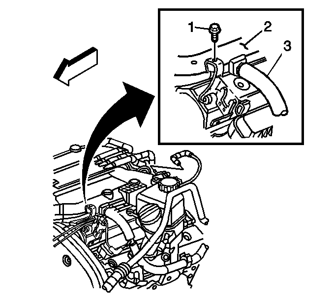
| • | The camshaft position (CMP) sensor connector |
| • | The left knock sensor connector |
| • | The vacuum pipe retainer |
| • | The intake plenum (2) |
| • | The engine rear lift bracket |
Installation Procedure
- Position the throttle body heater inlet hose/pipe to the engine.
- Connect the throttle body heater inlet hose to the throttle body.
- Install the bolts securing the throttle body heater inlet hose/pipe to the following:
- Connect the vacuum brake booster hose (3) to the vacuum source.
- Connect the following to the front of the throttle body heater inlet hose/pipe:
- Connect the electrical connector (2) to the coil pack (1).
- Connect the throttle body heater inlet hose to the water crossover, using 90° needlenose pliers.
- Connect the heated oxygen sensor connector (2) to the rear of the throttle body heater inlet hose/pipe (3).
- Install the wiper motor module. Refer to Windshield Wiper System Module Replacement in Wipers/Washer Systems.
- Install the remote power steering fluid reservoir mounting bolts (1, 3).
- Connect the following to the remote power steering fluid reservoir (1):
- Fill the cooling system. Refer to Cooling System Draining and Filling .

Notice: Refer to Fastener Notice in the Preface section.

| • | The intake plenum (2) |
| • | The engine rear lift bracket |
Tighten
Tighten the throttle body heater inlet hose/pipe bolts to 9 N·m (80 lb in).
| • | The CMP sensor connector |
| • | The left knock sensor connector |
| • | The vacuum pipe retainer |


Tighten
| • | Tighten the remote power steering fluid reservoir to intake plenum mounting bolts to 9 N·m (80 lb in). |
| • | Tighten the remote power steering fluid reservoir to cylinder head mounting bolt to 25 N·m (18 lb ft). |

| • | The brake booster hose |
| • | The wiring harness (2) |
Throttle Body Heater Inlet Hose/Pipe Replacement LS6
Removal Procedure
- Partially drain the cooling system. Refer to Cooling System Draining and Filling .
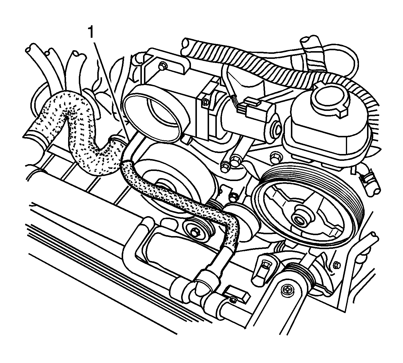
- Compress the clamp and remove the surge tank inlet hose from the surge tank.
- Remove the radiator shelf cover.
- Compress the clamp and remove the surge tank inlet hose from the radiator.
- Remove the surge tank inlet hose from the retaining features on the fan shroud and the air cleaner assembly.
- Compress the clamp and remove the surge tank inlet hose from the throttle body.
- Remove the surge tank inlet hose from the vehicle.
Installation Procedure
- Connect the surge tank inlet hose and clamp to the throttle body.
- Insert the surge tank inlet hose into the retaining features on the fan shroud and the air cleaner housing assembly.
- Connect the surge tank inlet hose and clamp to the radiator.
- Install the radiator shelf cover.
- Connect the surge tank inlet hose and clamp to the surge tank.
- Fill the cooling system. Refer to Cooling System Draining and Filling .

