Water Pump Replacement LA3, LY9
Removal Procedure
- Drain the cooling system. Refer to Cooling System Draining and Filling .
- Remove the timing belt cover. Refer to Timing Belt Cover Replacement in Engine Mechanical-2.6L and 3.2L.
- Remove the water pump bolts.
- Remove the water pump and seal.
- Clean the water pump mating surfaces.
- Clean and inspect the water pump. Refer to Water Pump Cleaning and Inspection in Engine Mechanical-2.6L and 3.2L.
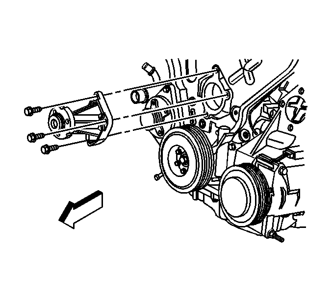
Important: Use a catch basin to collect escaping coolant.
Do not reuse the seal.
Installation Procedure
- Coat the seal ring of the water pump with silicone grease, GM P/N 12345579 (Canadian P/N 1974984) or equivalent.
- Install the O-ring seal to the water pump.
- Install the water pump into the engine block.
- Install the water pump bolts.
- Install the timing belt cover. Refer to Timing Belt Cover Replacement in Engine Mechanical-2.6L and 3.2L.
- Fill the cooling system. Refer to Cooling System Draining and Filling .
Important: Ensure the O-ring seal is properly positioned to the water pump.

Notice: Refer to Fastener Notice in the Preface section.
Tighten
Tighten the water pump bolts to 25 N·m (18 lb ft).
Water Pump Replacement LY7
Tools Required
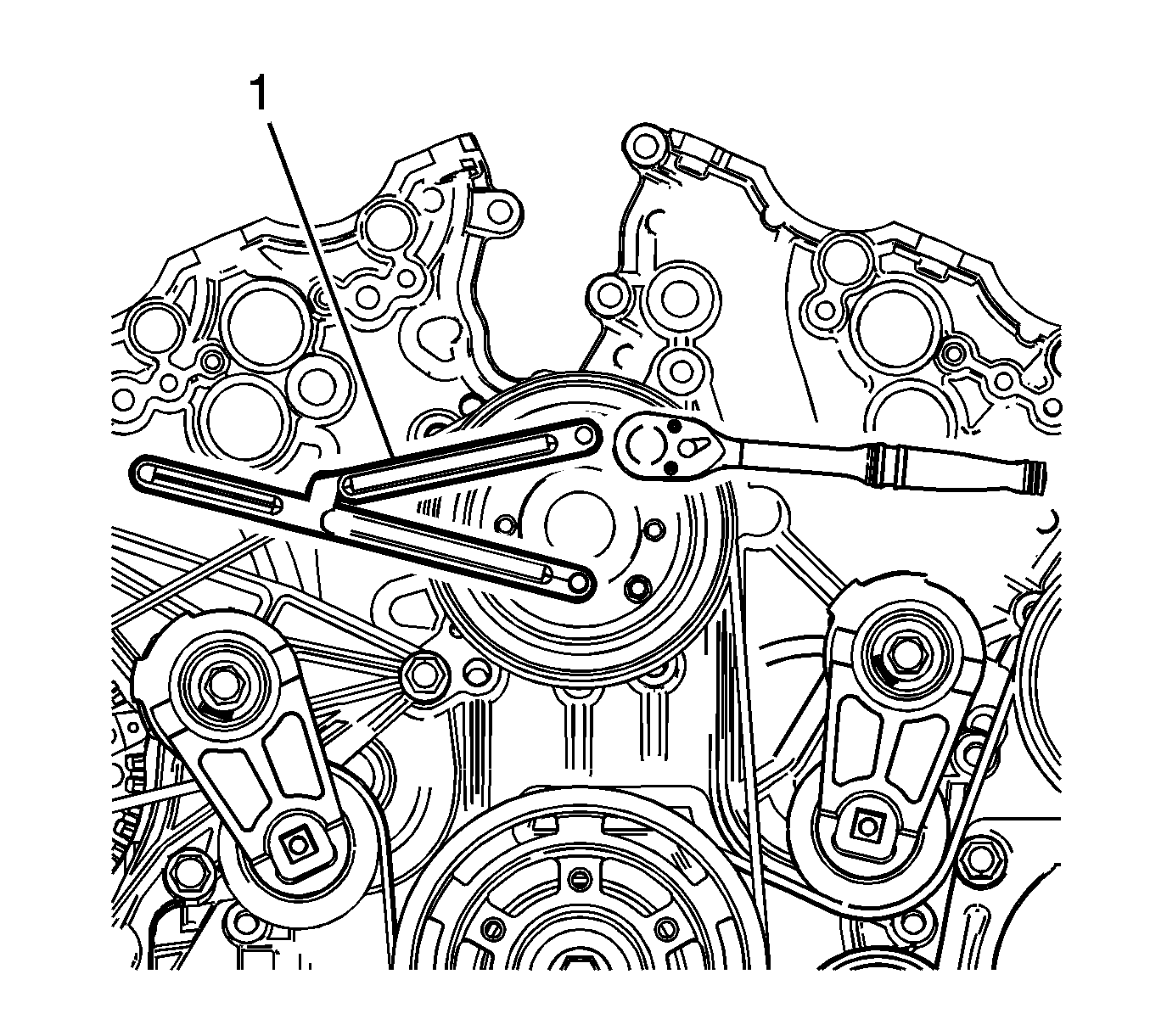
EN 46104 Water Pump Pulley Holding Tool
Removal Procedure
- Drain the cooling system. Refer to Cooling System Draining and Filling .
- Remove the generator drive belt. Refer to Water Pump and Generator Belt Replacement .
- Use the EN 46104 (1) in order to retain the water pump pulley.
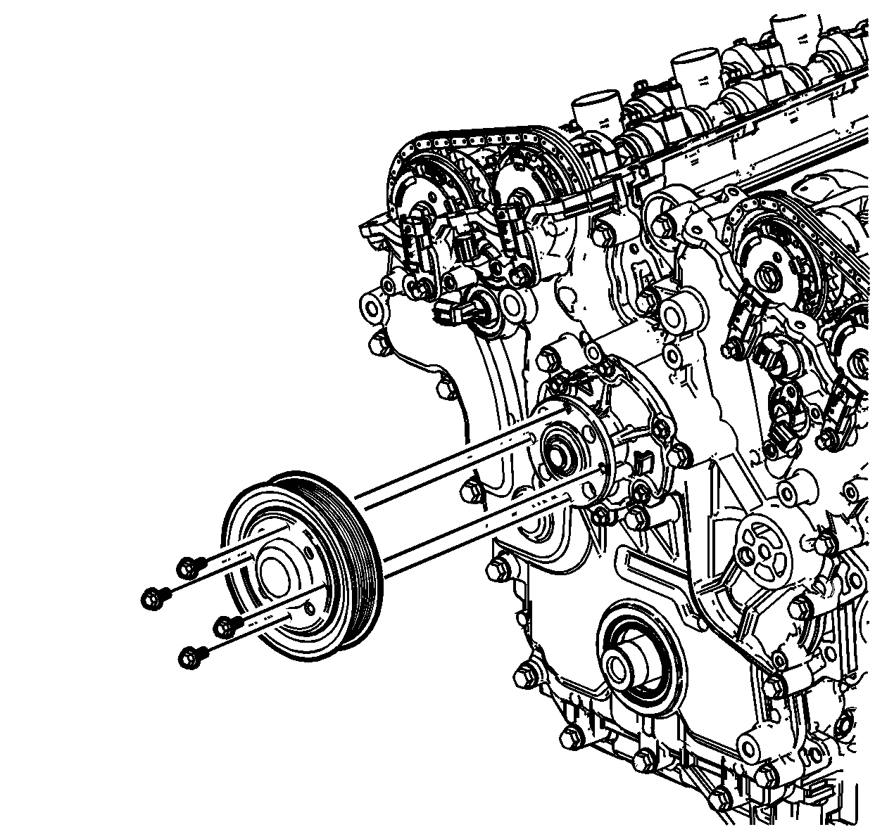
- Remove the water pump pulley bolts.
- Remove the water pump pulley.
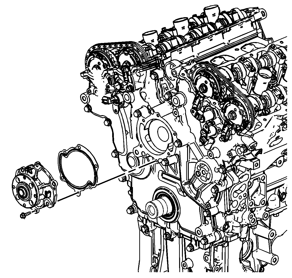
- Remove the water pump bolts.
- Remove the water pump.
- Remove and DISCARD the water pump seal.
- Carefully clean the water pump sealing surfaces.
Installation Procedure
- Install a NEW water pump seal.
- Install the water pump.
- Install the water pump bolts.
- Install the water pump pulley and the water pump pulley bolts.
- Use the EN 46104 (1) in order to retain the water pump pulley.
- Install the water pump pulley bolts.
- Install the generator drive belt. Refer to Water Pump and Generator Belt Replacement .
- Fill the cooling system. Refer to Cooling System Draining and Filling .

Notice: Refer to Fastener Notice in the Preface section.
Tighten
Tighten the water pump bolts to 10 N·m (89 lb in).


Tighten
Tighten the water pump pulley bolts to 12 N·m (106 lb in).
Water Pump Replacement LS6
Removal Procedure
- Remove the air cleaner outlet duct. Refer to Air Cleaner Outlet Duct Replacement in Engine Controls - 5.7L.
- Drain the cooling system. Refer to Cooling System Draining and Filling .
- Remove the cooling fan assembly. Refer to Engine Cooling Fan Replacement .
- Remove the accessory drive belt. Refer to Drive Belt Replacement - Accessory in Engine Mechanical - 5.7L.
- Reposition the inlet and outlet hose clamps at the water pump.
- Remove the inlet and outlet hoses from the water pump.
- Reposition the heater inlet and surge tank outlet hose clamps at the water pump.
- Remove the heater inlet and surge tank outlet hoses from the water pump.
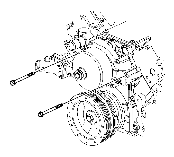
- Remove the water pump bolts.
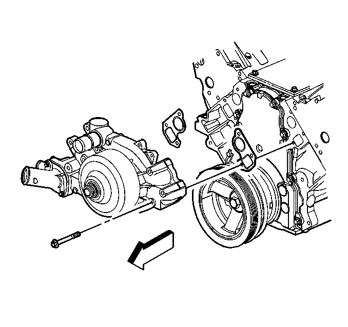
- Remove the water pump.
- Remove the water pump gaskets.
- Clean and inspect the water pump. Refer to Water Pump Cleaning and Inspection in Engine Mechanical - 5.7L.


Installation Procedure
- Install the water pump and gaskets to the engine block.
- Install the water pump bolts.
- Tighten the water pump bolts a first pass to 15 N·m (11 lb ft).
- Tighten the water pump bolts a final pass to 30 N·m (22 lb ft).
- Install the heater inlet and surge tank outlet hoses to the water pump.
- Position the heater inlet and surge tank outlet hose clamps at the water pump.
- Install the inlet and outlet hoses to the water pump.
- Position the inlet and outlet hose clamps at the water pump.
- Install the accessory drive belt. Refer to Drive Belt Replacement - Accessory in Engine Mechanical - 5.7L.
- Install the cooling fan assembly. Refer to Engine Cooling Fan Replacement .
- Fill the cooling system. Refer to Cooling System Draining and Filling .
- Install the air cleaner outlet duct. Refer to Air Cleaner Outlet Duct Replacement in Engine Controls - 5.7L.


Notice: Use the correct fastener in the correct location. Replacement fasteners must be the correct part number for that application. Fasteners requiring replacement or fasteners requiring the use of thread locking compound or sealant are identified in the service procedure. Do not use paints, lubricants, or corrosion inhibitors on fasteners or fastener joint surfaces unless specified. These coatings affect fastener torque and joint clamping force and may damage the fastener. Use the correct tightening sequence and specifications when installing fasteners in order to avoid damage to parts and systems.
Tighten


