CAUSES OF ECM CODE 55 PROCEDURE TO ERASE/ REPAIR

VEHICLES AFFECTED: 1987 CADILLAC ALLANTE
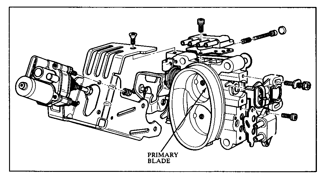
Some 1987 Allante vehicles may set a current ECM Code E055 (TPS misadjusted) that cannot be cleared using ECM clear codes in diagnostics. To clear a current Code E055 on an Allante, the negative battery cable must be disconnected for 10 seconds.
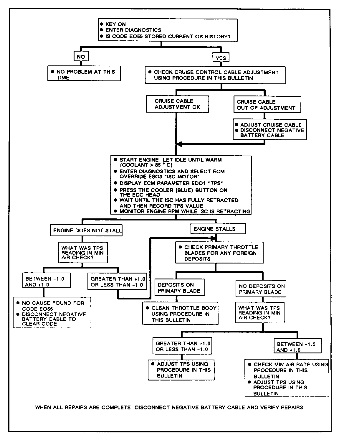
It is important that the cause for a history or current Code E055 be found using the trouble tree provided in this bulletin. The trouble tree will determine if the (2ode E055 was set due to:
1. Misadjusted cruise control cable.
2. Throttle body primary blade deposits (coking).
3. Misadjusted TPS.
Repair procedures for each of these causes are also included in this bulletin.
The ECM tests for a Code E055 when the ignition is turned off. The ECM then retracts the ISC motor until the throttle rests on the minimum air screw. The ECM looks at TPS voltage to determine if the TPS is misadjusted. Two consecutive ignition off cycles with TPS voltage outside of a calibrated range (plus or minus 3 degrees) will set Code E055. The ECM won't test for Code E055 unless the engine has been running for 10 minutes with the coolant temperature above 70 degrees C during the ignition cycle. Therefore, the ECM will keep a Code E055 current even if the ECM codes are cleared in diagnostics. The negative battery cable must be disconnected for 10 seconds (reset ECM memory) to clear a current Code E055.
1. Key ON, Engine OFF.
2. Enter diagnostics and select ECM override ES03 "ISC MOTOR".
3. Press the cooler button to retract the ISC to the minimum air throttle stop.
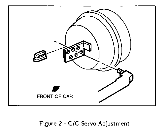
4. Note what servo blade hole the cruise cable is adjusted to.
5. Disconnect the cable from the servo blade.
6. Remove slack from cable (pull lightly on cable without moving throttle).
7. Reconnect the cable in the next loosest hole (closer to the throttle body).
8. If this hole is the same as the original adjustment, cruise cable adjustment is OK.
9. If the new hole is different than the original adjustment, cruise cable was out of adjustment.
THROTTLE BODY CLEANING PROCEDURE
1. Remove the air intake duct from the throttle body.
2. Clean the primary throttle bore and the area behind and around the throttle plate using a clean shop towel with GM Top Engine Cleaner (P/N 1052626) or AC-Delco Carburetor Tune-up Conditioner (P/N X66-P) or equivalent product. DO NOT USE ANY SOLVENT THAT CONTAINS METHYL ETHYL KETONE.
NOTE: DO NOT CLEAN THE SECONDARY THROTTLE BLADE.
3. Disconnect the negative battery cable to reset learned TPS value.
4. Recheck TPS value with ISC retracted to assure TPS, parameter (ED01) is within -1.0 to +1.0 limits.
MINIMUM AIR RPM CHECK Preliminary Checks:
1. Enter diagnostics and record all trouble codes displayed. If current or history codes are found, see "Diagnosis Procedures" in Section 8D. When all trouble codes are repaired, proceed to step 2.
2. Perform PFI system check in Section 6E, Subsection A. If the chart leads to "Fuel System is Controlling", proceed to step 3.
3. Start the engine. Enter diagnostics. Select ECM data ED04 "Coolant Temperature". Operate the engine until coolant temperature is greater than 85 degrees C.
4. Perform ECM input test EI72 and EI74. Refer to the trouble tree in Section 8DI for diagnosis if input does not cycle. If both inputs cycle, proceed to step 5.
5. Exit diagnostics. Select the "OFF" mode on the CCDIC. Wait 10 seconds, then re-enter diagnostics. Place the steering wheel in its center position. Place the transmission in park.
6. Enter set timing mode by jumpering Pin A to B of the ALDL connector. Check for timing at 10 degrees BTDC and adjust as necessary. Disconnect the jumper at the ALDL and reinstall the connector cover. Ensure that the cover is latched.
7. Visually check all vacuum hoses for splits, leaks, or cuts and assure that there are no vacuum leaks.
8. Enter diagnostics and select ECM override ES03 "ISC MOTOR".
9. Press the cooler button to retract the ISC motor. When fully retracted, check minimum air idle RPM.
10. Minimum idle RPM should be:
450-550 if odometer is less than 800 km 450-600 if odometer is greater than 800 km
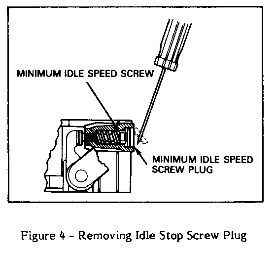
If the minimum idle speed is out of these RPM limits, connect a tachometer to the engine and adjust the minimum idle speed screw to 500 RPM. Remove and discard the minimum idle speed screw plug. Use a T-20 torx driver to adjust the minimum idle speed screw. If the engine speed cannot be corrected, check that the throttle is not held off the minimum idle speed screw because of linkage binding or interference with the ISC motor plunger. Also check vacuum hoses for leaks, for air leaks at throttle body mounting and intake manifold. After adjusting minimum idle speed, proceed to TPS adjustment procedure.
TPS ADJUSTMENT PROCEDURE
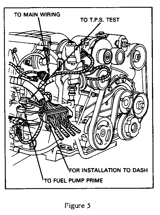
1. If the throttle angle displayed is outside the -1.0 to +1.0 band, measure the TPS signal voltage by connecting a high impedance digital voltmeter to the TPS test point located by the right shock tower. With the meter set to the two volt scale, connect the meter positive lead to CKT 417, dark blue wire, and the negative lead to CKT 476, black/white wire (Figure 5).
With engine still running, loosen the TPS screws ]Ust enough to permit the sensor to be rotated. A T-25 torx driver should be used for TPS adjustment. Adjust the TPS so that voltmeter reads .475-.525 volts. Tighten the TPS mounting screws with the sensor in the adjusted position. Recheck ECM data ED01 to be sure that the TPS angle is -1.0 to +1.0.
IMPORTANT: Do not use excessive force (don't pound or pry) to adjust the TPS or damage to the TPS may occur. The TPS mounting screw must be loosened to perform the adjustment.
ISC Maximum Extension Check and Adjustment:
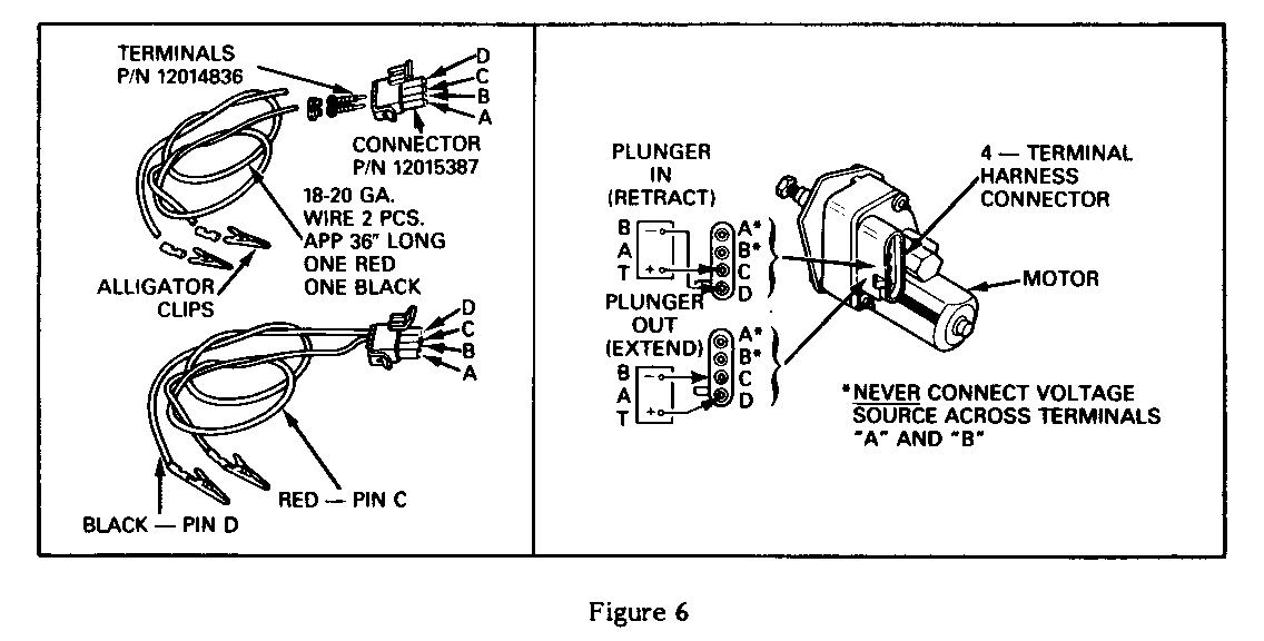
2. With the key "ON", engine "OFF", extend the ISC motor as described in the jumper harness procedure (Figure 6).
3. With the meter set to the two volt scale, connect the meter positive lead to CKT 417, dark blue wire, and the negative lead to CKT 476, black/white wire. Momentarily apply voltage to extend the ISC motor, noting the voltmeter value with the ISC stopped. Do this several times. With the ISC stopped at full extension, one of two voltmeter values will be seen; a high value at the top of the ratchet and a low value at the bottom of the ratchet.
Look for the highest TPS voltage, which will be seen when the ISC stops at the top of its ratchet. Stop the ISC when the highest TPS voltage is seen.
4. If the TPS voltage is 1.225-1.325 volts, no adjustment is needed. If the voltage is out of this range, adjust the ISC plunger by turning the plunger in to lower the voltage or out to raise the voltage. Recheck the maximum extension voltage by again applying power to extend the ISC until a maximum TPS voltage is seen.
After All Checks and Adjustments are Completed:
5. Retract the ISC motor plunger halfway before proceeding.
6. Disconnect all test equipment and reconnect the ISC motor connector. Turn the key "OFF" for at least 10 seconds. Start the engine and check the ISC motor for proper operation.
7. The above procedure may have turned on a telltale light or set an ECM or BCM code. Enter diagnostics and clear all stored ECM and BCM codes.
To Retract the ISC Plunger:
1. Enter diagnostics and select ECM override ES03 "ISC MOTOR".
2. Press the cooler button on the CCDIC.
3. Wait approximately 20 seconds for ISC plunger to fully retract.
To Extend the ISC Plunger:
1. Connect ISC terminal "D" to 12 volts at the battery or junction block.
2. Connect the ISC terminal "C" to ground until the ISC plunger is partially or fully extended.
IMPORTANT: If the ISC motor fails to extend, disconnect and reconnect terminal "C" to ground to "bump" the motor from its stalled fully retracted position.
General Motors bulletins are intended for use by professional technicians, not a "do-it-yourselfer". They are written to inform those technicians of conditions that may occur on some vehicles, or to provide information that could assist in the proper service of a vehicle. Properly trained technicians have the equipment, tools, safety instructions and know-how to do a job properly and safely. If a condition is described, do not assume that the bulletin applies to your vehicle, or that your vehicle will have that condition. See a General Motors dealer servicing your brand of General Motors vehicle for information on whether your vehicle may benefit from the information.
