For 1990-2009 cars only
Removal Procedure
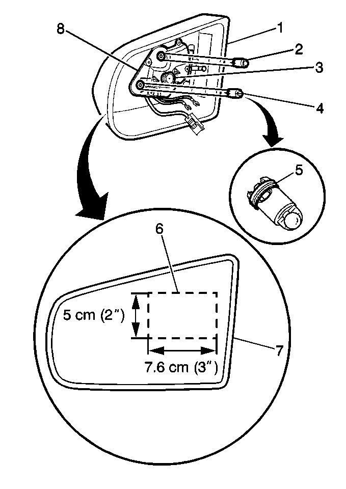
- Remove the mirror and the plastic backing plate (7) by pulling the assembly out of the mirror housing (1).
- Verify that the springs (5) on the actuator shafts (2,4) are not pushed down on the shafts.
- Ensure that the springs (5) are seated in the grooves.
- Disconnect the electrical connectors.

Important: Verify that the springs (5) on the actuator shafts (2,4) are not pushed down on the shafts.
Installation Procedure
- Snap the actuator shafts (2,4) into the power drive unit (8).
- Connect the electrical connectors.
- Rotate the actuator shafts (2,4) in order to align the ears with the corresponding slots in the back side of the mirror face (7).
- Align the swivel (3) on the power drive unit (8) to the pivot points on the mirror backing plate.
- Using the block (6), perform the following procedure:
- Inspect the mirror for proper operation.

Notice: To avoid damaging electrochromic mirrors, yellowing and/or silver delamination, pressure must not be applied to the center of the mirror. Place a 6 x 9 cm (2 x 3 in) block of wood in the indicated target area. This will distribute pressure evenly.
| 5.1. | Push in on the block (6) until you hear a snap. |
| 5.2. | Tilt the mirror (7) towards the upper actuator shaft (2). |
Apply pressure on the block until the ratchet sound stops.
| 5.3. | Tilt the mirror (7) towards the outside actuator shaft (4). |
Apply pressure on the block until the ratchet sound stops.
If the mirror is not operating properly, inspect the actuator shaft alignments again.
