For 1990-2009 cars only
- Remove the left sound insulator. Refer to Instrument Panel Insulator Panel Replacement - Left Side in Instrument Panel, Gauges and Console.
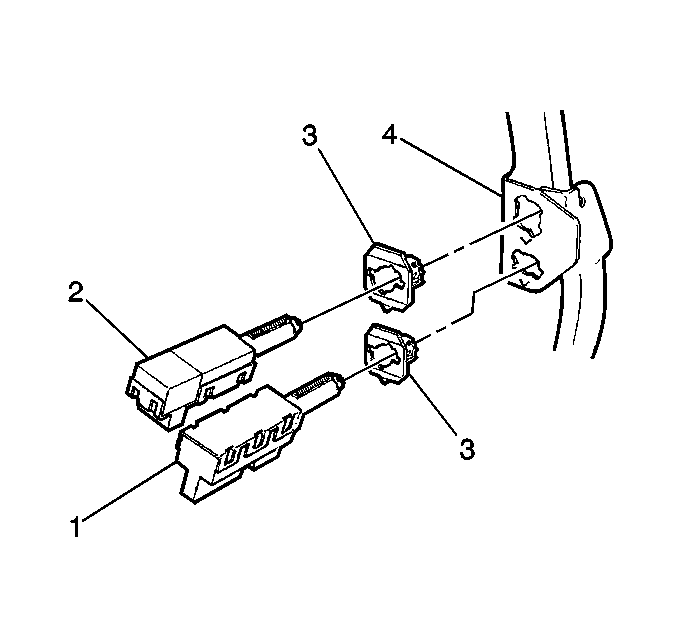
- Insert the release switch (1) into the retainer (3) until the switch is fully seated against the brake pedal arm.
- Twist the switch (1) in order to lock the switch into position.
- Measure the distance from the end of the barrel on the switch to the pedal arm. Ensure that the clearance is 1.5-1.7 mm (1/16 in). If the measurement is incorrect, perform steps 1 and 2 again.
- Ensure that the following components close at 3.5-12.5 mm (0.125-0.5 in) of brake pedal travel:
- Install the left sound insulator. Refer to Instrument Panel Insulator Panel Replacement - Left Side in Instrument Panel, Gauges and Console.

Important:
• Do not adjust the TCC/ABS (1) or the stoplamp/BTSI (2)
switches until you have connected the brake booster push rod to the brake
pedal assembly. • Adjust the TCC/ABS (1) and the stoplamp/BTSI (2)
switches together. • Incorrect adjustment of any of these components may cause the
cruise control system to work improperly. • For more information about the stoplamp switch replacement, refer
to
Stop Lamp Switch Replacement
in Hydraulic Brakes. • DO NOT depress the brake pedal during the following adjustment
procedure.
Notice: Proper stoplamp switch adjustment is essential. Improper stoplamp switch adjustment could cause brake drag and excessive brake lining wear.
| • | The contacts on the release switch assembly (1) |
| • | The contacts on the stoplamp switch assembly (2) |
| • | Measure this travel at the centerline of the brake pedal assembly pad. The nominal actuation of the stoplamp switch assembly contacts is about 4.5 mm (3/16 in). |
