Air Conditioning Clutch Coil Removal HT6/HD6/HU6
Tools Required
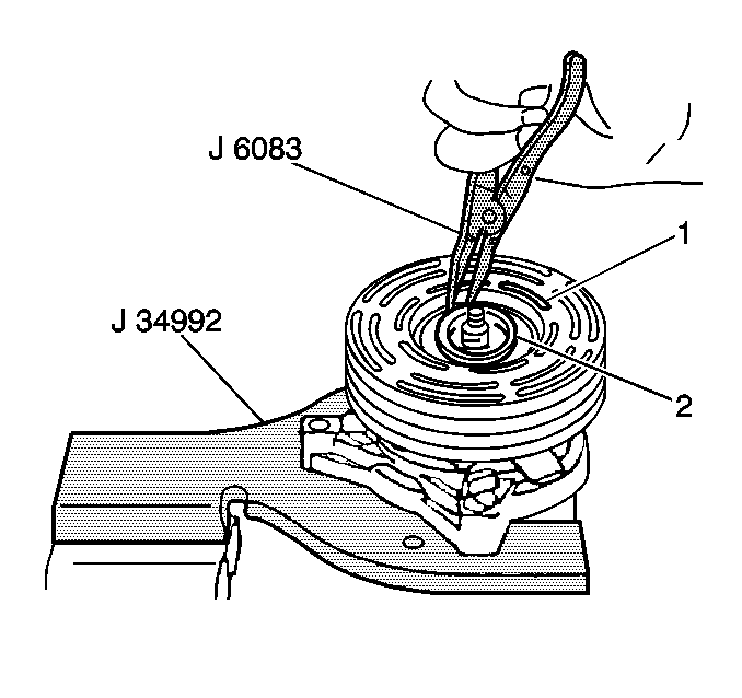
- Remove the clutch plate
and hub assembly. Refer to Compressor Clutch Plate and Hub Assembly Removal (HT6/HD6)
.
- Use the J 6083
in
order to remove the following components:
| • | The bearing assembly retaining ring (2) |
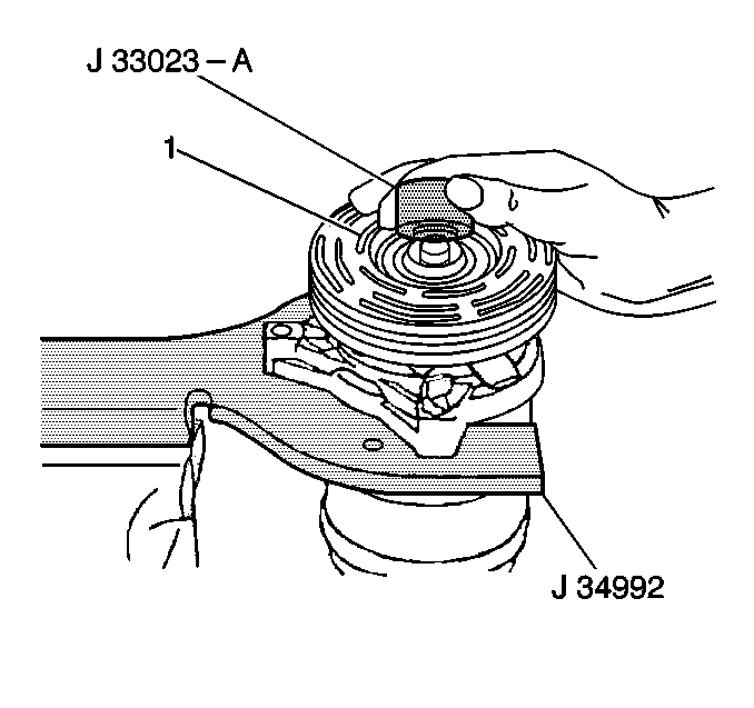
- Install the J 33023-A
to the front head.
- Install the J 41552
down into the inner circle of slots (1) in the rotor.
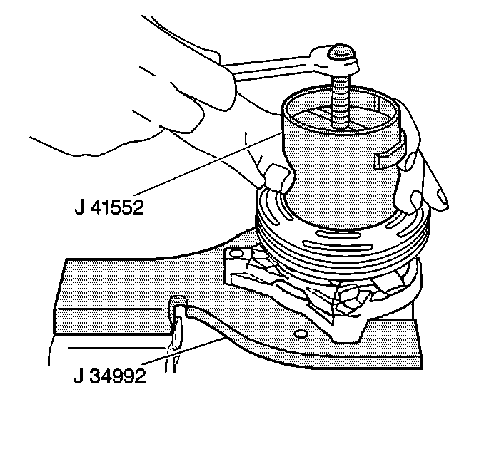
- Turn the J 41552
clockwise
in the slots in the rotor.
- Perform the following steps in order to remove the pulley rotor
and bearing assembly:
| 6.2. | Tighten the puller screw against the puller guide. |
| 6.3. | Remove the pulley rotor and bearing assembly. |

- Mark the clutch coil terminal
location (1) on the compressor front head. Clutch Rotor and/or Bearing Removal (HT6/HD6)
.
- Install the J 33023-A
on the front head of the compressor.
- Install the J 8433-1
and the J 33025
.
- Tighten the J 8433-3
against the puller pilot in order to remove the clutch coil (2).
Air Conditioning Clutch Coil Removal V5 - Conventional Mount
Tools Required
| • | J 6083 Snap
Ring Pliers #24 External |
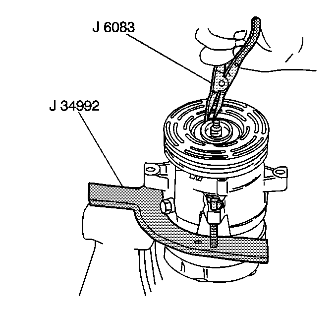
- Remove the clutch plate
and hub assembly. Refer to Compressor Clutch
Plate and Hub Assembly Removal (V5 -- Conventional Mount)
.
- Use the J 6083
in
order to remove the rotor and bearing assembly retaining ring.
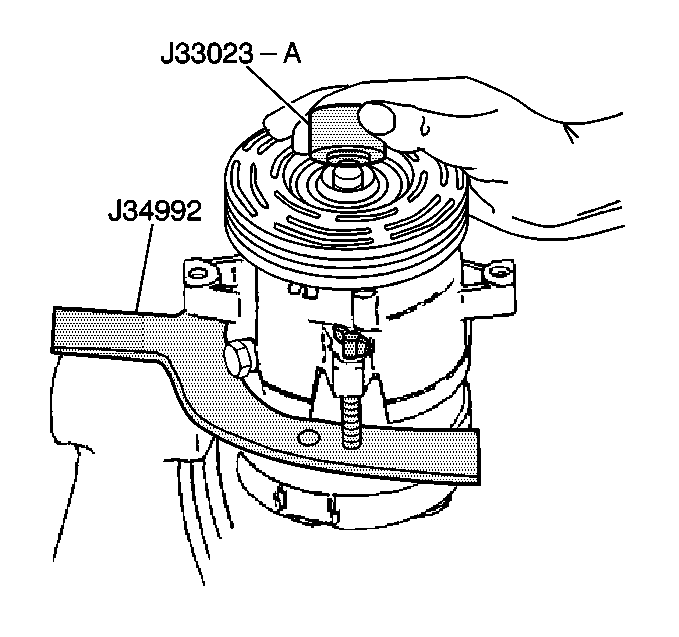
- Install the J 33023-A
to the front head.
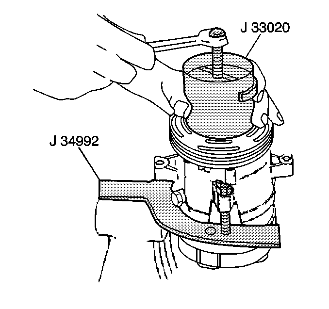
- Install the J 33020
into
the inner circle of slots in the rotor.
- Turn the J 33020
clockwise in the slots in order to engage the tangs of the puller
with the segments between the slots in the rotor.
- Hold the J 33020
in place. Tighten the puller screw against the puller guide in order
to remove the puller rotor and bearing assembly.
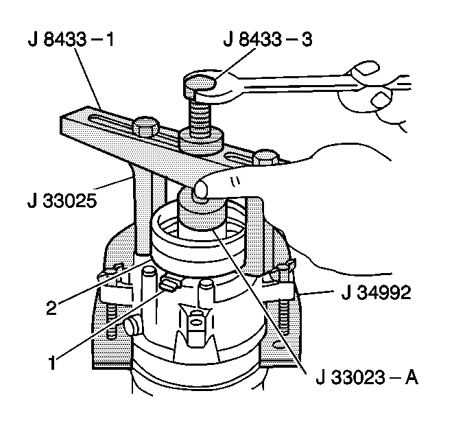
- Mark the location of the clutch coil terminal (1) on the compressor
front head.
- Install the J 33023-A
on the front head of the compressor.
- Install the J 8433-1
and theJ 8433-3
with
the J 33025
on the front
head of the compressor.
- Tighten the J 8433-3
against the J 33023-A
in
order to remove the clutch coil (2).


