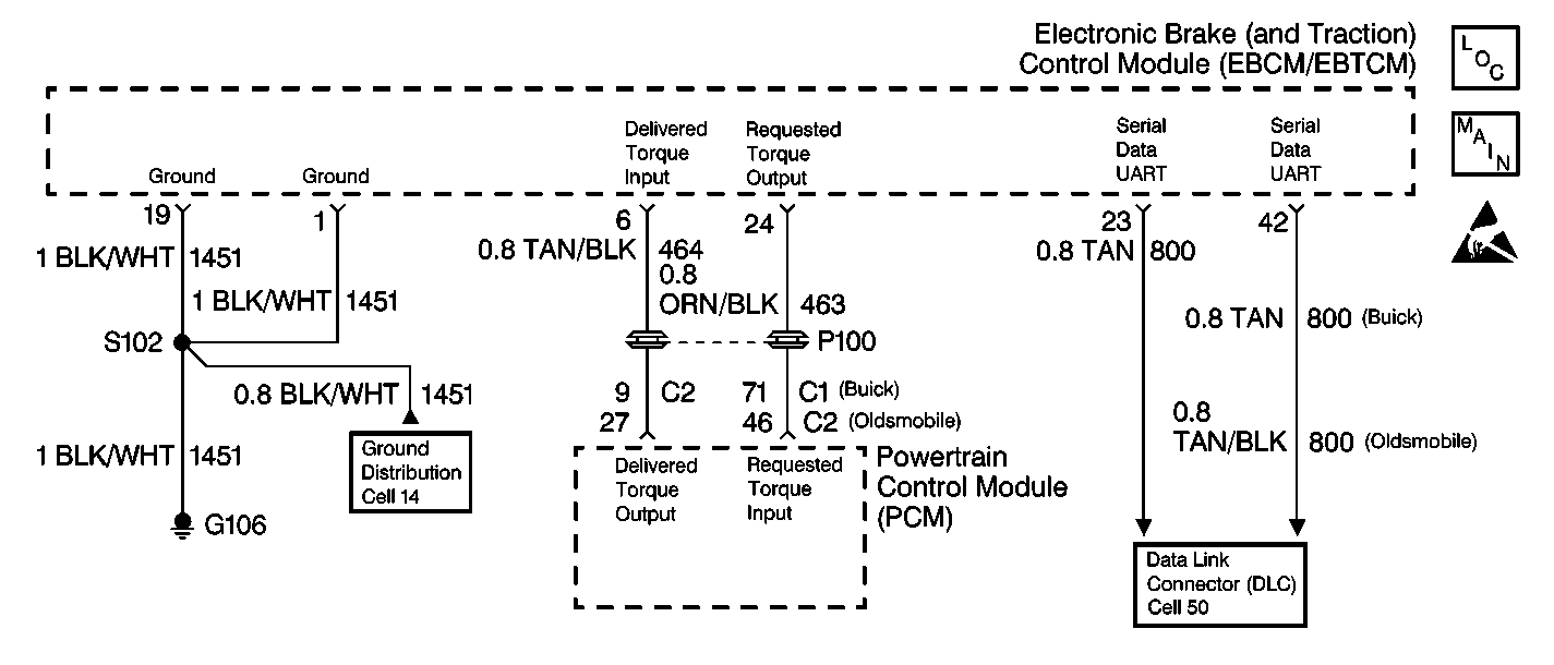
Circuit Description
The serial data link is a communication line between the PCM, the EBTCM and the other system controllers.
The EBTCM shares specific serial data information supplied on the data line. The data line also allows the use of a bi-directional Scan Tool.
Conditions for Setting the DTC
The DTC C1276 can be set any time when the ignition is in RUN.
A malfunction exists if CKT 800 is open or shorted to ground. This malfunction results in a loss of communication to the PCM or to any other controller.
A current DTC C1276 cannot be read with a Scan Tool. This is due to the loss of serial data communications.
After communications are restored to the data line, the DTC C1276 will be stored in the memory.
Action Taken When the DTC Sets
The following actions are taken when the DTC sets:
| • | A malfunction DTC is stored. |
| • | The TCS is disabled. |
| • | The TRACTION OFF indicator lamp is turned ON. |
Conditions for Clearing the DTC
The DTC will clear under following conditions:
| • | Conditions for the malfunction are no longer present. Use the scan tool Clear DTCs function. |
| • | 100 ignition switch key cycles have passed without detecting any malfunctions |
Diagnostic Aids
The malfunction may be intermittent.
Try wiggling the wires and the connectors while performing the tests. This often causes the malfunction to appear.
A PCM DTC will probably be set along with the DTC C1276.
Inspect the following grounds thoroughly:
| • | G101 |
| • | G102 |
| • | G106 |
| • | G110 |
The DTC C1276 can only be read as a history code. This is because the scan tool uses the same serial data circuit.
If CKT 800 is shorted to the ground or open, communication with the scan tool will not be possible.
Step | Action | Value(s) | Yes | No |
|---|---|---|---|---|
1 | Was the Diagnostic System Check performed? | -- | Go to Diagnostic System Check | |
2 | Connect the scan tool. Can the scan tool communicate with any controller other than the EBCM/EBTCM? | -- | Go to Diagnostic System Check | |
3 |
Is the resistance of either measurement less than the specified value? | 2 ohms | ||
4 | Repair the short to ground in CKT 800. Is the repair complete? | -- | Go to Diagnostic System Check | -- |
5 |
Is the resistance less than the specified value for both measurements? | 0-2 ohms | ||
6 | Repair the open or the high resistance in CKT 800. Refer to Wiring Repairs in Wiring Systems. Is the repair complete? | -- | Go to Diagnostic System Check | -- |
7 |
Is the voltage within the specified range? | Battery Voltage | ||
8 | Repair the short to voltage in CKT 800. Refer to Wiring Repairs in Wiring Systems. Is the repair complete? | -- | Go to Diagnostic System Check | -- |
9 | Suspect the PCM. Refer to Powertrain On Board Diagnostic (OBD) System Check in Engine Controls-3.8L or Powertrain On Board Diagnostic (OBD) System Check in Engine Controls-4.0L. Is the repair complete? | -- | Go to Diagnostic System Check | -- |
