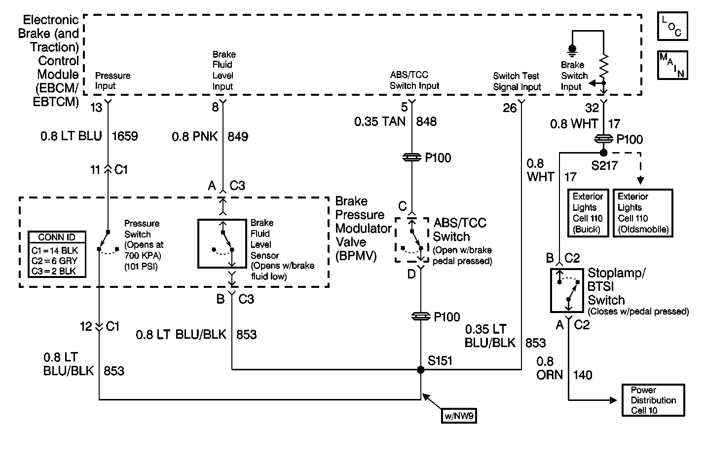
Circuit Description
| • | The EBCM/EBTCM monitors brake pedal position using the TCC/antilock brake switch. The switch, normally closed, opens when the brake pedal is depressed by 40 percent. The EBCM/EBTCM also monitors pump motor operation using a pump motor run sensor. |
| • | During most ABS braking conditions, the EBCM/EBTCM turns on the pump motor, replenishing the BPMV reservoir and applying fluid pressure to the master cylinder. This causes the brake pedal to rise gradually. The EBCM/EBTCM turns off the pump motor when the brake pedal height rises sufficiently to close the TCC/antilock brake switch. |
Conditions for Setting the DTC
| • | During ABS braking, the DTC C1262 sets when the EBCM/EBTCM determines that the pump is working, and that brake pedal height has not risen sufficiently in order to close the TCC/antilock brake switch after three seconds. |
| • | The following are possible causes of a hydraulic problem: |
| - | Air in the brake lines |
| - | A pump motor mechanical failure |
| • | The following are possible causes of a non-hydraulic problem: |
| - | An open CKT 848 or CKT 853 |
| - | An improperly adjusted or defective TCC/antilock brake switch |
Action Taken When the DTC Sets
| • | DTC C1262 is stored. |
| • | The ABS is disabled. |
| • | The ANTILOCK indicator lamp is turned on |
Conditions for Clearing the DTC
The DTC will clear under the following conditions:
| • | Conditions for the malfunction are no longer present. Use the scan tool Clear DTCs function. |
| • | 100 ignition switch key cycles have passed without detecting any malfunctions |
Diagnostic Aids
| • | The following conditions are other possible causes of this malfunction: |
| - | A malfunctioning TCC/Antilock switch. |
| - | A malfunctioning ABS pump relay or ABS main relay |
| • | Failure to carefully inspect wiring may result in a misdiagnosis. A misdiagnosis may result in replacing parts without repairing the malfunction. |
Step | Action | Value(s) | Yes | No |
|---|---|---|---|---|
1 | Was the Diagnostic System Check Performed? | -- | Go to Diagnostic System Check | |
2 |
Did the brake pedal rise? | -- | ||
3 |
Did DTC C1262 reset? | -- | Go to Diagnostic System Check | |
4 |
Is the switch adjusted properly? | -- | ||
5 |
Is the resistance less than the specified value? | 2 ohms | ||
6 |
Is the resistance less than the specified value? | 2 ohms | ||
7 | Use the J 39200 in order to measure the distance between the J 38716 pinout box terminal 26 and the TCC/antilock brake switch harness connector terminal D. Is the resistance less than the specified value? | 2 ohms | ||
8 | Adjust the TCC/antilock brake switch. Refer to Brake Release Switch Adjustment in Cruise Control. Is the repair complete? | -- | Go to Diagnostic System Check | -- |
9 | Repair the open or high resistance in CKT 848. Is the repair complete? | -- | Go to Diagnostic System Check | -- |
10 | Repair the open or high resistance in CKT 853. Refer to Wiring Repairs in Wiring Systems. Is the repair complete? | -- | Go to Diagnostic System Check | -- |
11 | Replace the TCC/Antilock Brake Switch. Refer to Brake Release Switch Adjustment in Cruise Control. Is the repair complete? | -- | Go to Diagnostic System Check | -- |
12 | Replace the BPMV. Refer to Brake Pressure Modulator Valve Replacement . Is the repair complete? | -- | Go to Diagnostic System Check | -- |
13 | Replace the EBCM/EBTCM. Refer to Electronic Brake and Traction Control Module Replacement . Is the repair complete? | -- | Go to Diagnostic System Check | -- |
