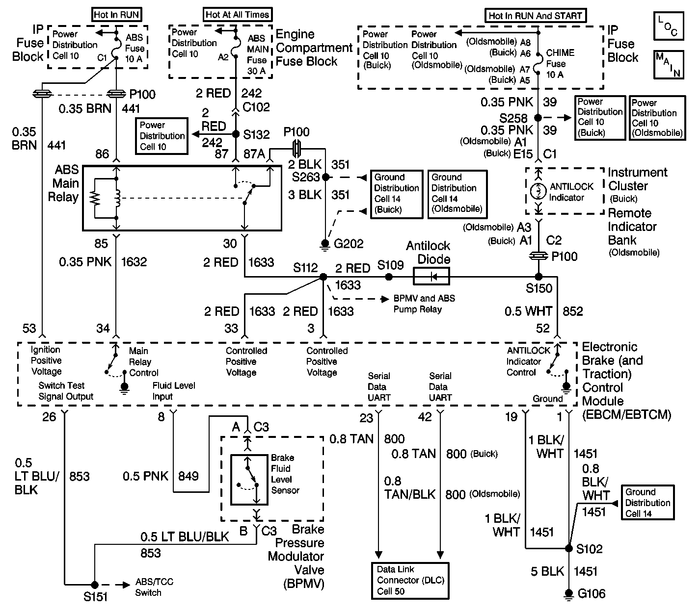
Circuit Description
When the ignition switch is first turned to the RUN position, the EBCM/EBTCM goes through a self-test lasting 2-4 seconds. During this test, the EBCM/EBTCM grounds terminal 52, causing the amber ANTILOCK indicator to light. This serves as an indicator bulb test. The EBCM/EBTCM also grounds terminal 34, energizing the main relay. This removes the indicator ground path provided through the antilock diode and the main relay contacts.
When the self-test is completed (and no faults detected) the EBCM/EBTCM removes the ground at terminal 52, turning OFF the indicator. The main relay remains energized.
When the EBCM/EBTCM detects a malfunction, it grounds terminal 52 causing the amber ANTILOCK indicator to light. (Note: The EBCM/EBTCM also de-energizes the main relay creating a redundant ground path.)
When the EBCM/EBTCM is disabled for any reason (i.e., open ABS fuse), the main relay is de-energized. This provides an ANTILOCK indicator ground path through the antilock diode and main relay contacts, and causes the indicator to come ON with no DTC being set.
Diagnostic Aids
Possible causes:
| • | Open in CKT 1451, 852, 39, 351, or 1633. |
| • | Open IGN 1 fuse (Buick) or CADME Fuse (Oldsmobile). |
| • | Open bulb. |
| • | Short to voltage in CKT 852. |
| • | Open or shorted antilock diode. |
| • | Main relay fails "engaged." |
| • | Short to ground in CKT 39, 852, or 1632. |
Step | Action | Value(s) | Yes | No |
|---|---|---|---|---|
1 | Was the Diagnostic System Check performed? | -- | Go to Step 2 | Go to Diagnostic System Check |
2 |
Is the resistance less than the specified value? | 2 ohms | Go to Step 3 | Go to Step 11 |
3 |
Is the voltage within the specified range? | Battery Voltage | Go to Step 4 | Go to Step 12 |
4 |
Does the ANTILOCK indicator illuminate? | -- | Go to Step 5 | Go to Step 17 |
5 |
Does diode check OK? | -- | Go to Step 6 | Go to Step 18 |
6 |
Does the ANTILOCK indicator illuminate for 2-4 seconds and then go out? | -- | Go to Diagnostic System Check | Go to Step 7 |
7 |
Is the resistance less than the specified range? | 2 ohms | Go to Step 8 | Go to Step 19 |
8 |
Is the voltage within the specified range? | Battery Voltage | Go to Step 9 | Go to Step 20 |
9 | Measure the voltage between the ABS main relay harness connector terminals 30 and 87A. Is the voltage within the specified range? | Battery Voltage | Go to Step 10 | Go to Step 21 |
10 |
Is the resistance less than the specified value? | 2 ohms | Go to Step 22 | Go to Step 23 |
11 | Repair the open or high resistance in CKT 1451. Refer to Wiring Repairs in Wiring Systems. Is the repair complete? | -- | Go to Diagnostic System Check | -- |
12 |
Is the fuse open? | -- | Go to Step 13 | Go to Step 14 |
13 | Repair the short to ground in CKT 39. Refer to Wiring Repairs in Wiring Systems. Is the repair complete? | -- | Go to Diagnostic System Check | -- |
14 | Remove and check the ANTILOCK indicator bulb. Is the bulb open? | -- | Go to Step 15 | Go to Step 16 |
15 | Replace the ANTILOCK indicator bulb. Is the repair complete? | -- | Go to Diagnostic System Check | -- |
16 | Repair the open or high resistance in CKT 39 or CKT 852. Refer to Wiring Repairs in Wiring Systems. Is the repair complete? | -- | Go to Diagnostic System Check | -- |
17 |
Is the repair complete? | -- | Go to Diagnostic System Check | -- |
18 | Replace antilock diode. Observe the polarity. Refer to Antilock Diode Replacement . Is the repair complete? | -- | Go to Diagnostic System Check | -- |
19 | Replace the ABS main relay. Refer to Wiring Repairs in Wiring Systems. Is the repair complete? | -- | Go to Diagnostic System Check | -- |
20 | Repair the open or high resistance in CKT 1633. Refer to Wiring Repairs in Wiring Systems. Is the repair complete? | -- | Go to Diagnostic System Check | -- |
21 | Repair the open or high resistance in CKT 351. Refer to Wiring Repairs in Wiring Systems. Is the repair complete? | -- | Go to Diagnostic System Check | -- |
22 | Repair the short to ground in CKT 1632. Refer to Wiring Repairs in Wiring Systems. Is the repair complete? | -- | Go to Diagnostic System Check | -- |
23 |
Does the system operate properly? | -- | Go to Diagnostic System Check | Go to Step 24 |
24 | Replace the EBCM/EBTCM. Refer to Electronic Brake and Traction Control Module Replacement . Is the repair complete? | -- | Go to Diagnostic System Check | -- |
