GM Service Manual Online
For 1990-2009 cars only
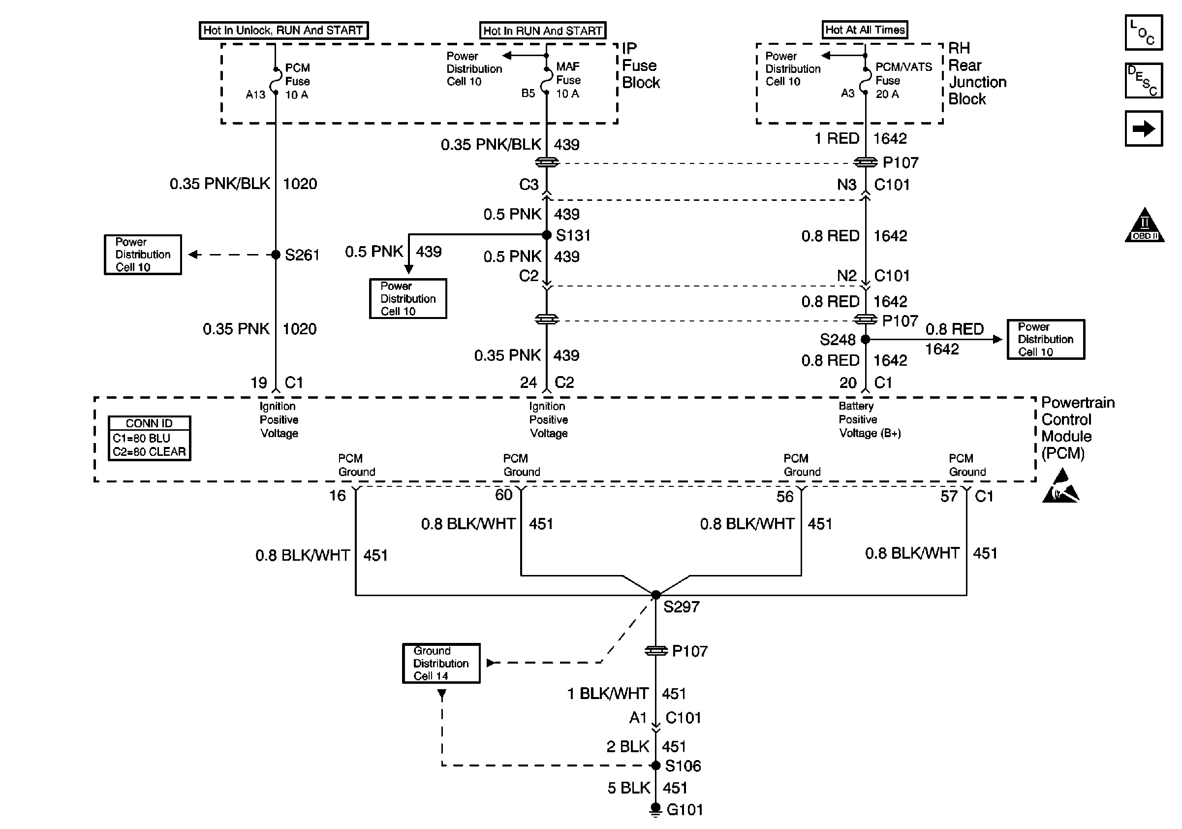
Figure 1:

Cell 20: PCM Power and Grounds


Object Number: 185980  Size: FS
Engine Controls Components
Powertrain Control Module Description
Cell 20: MIL Control, DLC
OBDII Symbol Description Notice
Power Distribution Schematics
Engine Controls Schematic References
Power Distribution Schematics
Ground Distribution Schematics
Power Distribution Schematics
Powertrain Control Module Connector End Views
Handling ESD Sensitive Parts Notice
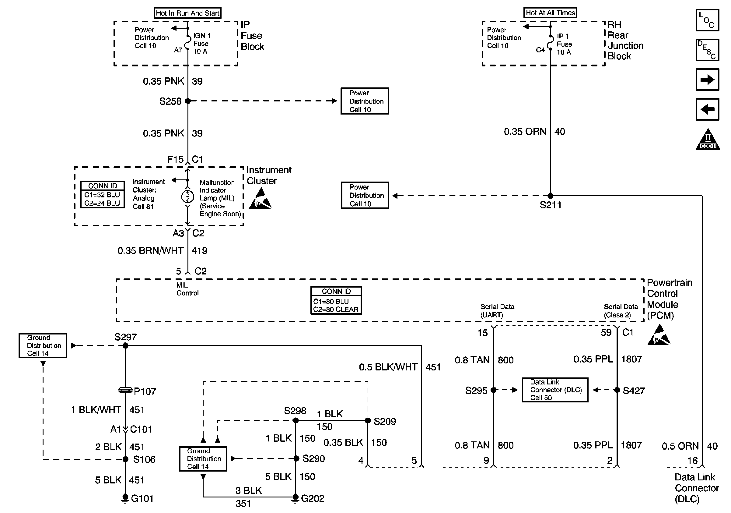
Figure 2:

Cell 20: MIL Control, DLC


Object Number: 185982  Size: FS
Engine Controls Components
Powertrain Control Module Description
Cell 20: Ignition Control Module
Cell 20: PCM Power and Grounds
OBDII Symbol Description Notice
Power Distribution Schematics
Handling ESD Sensitive Parts Notice
Engine Controls Schematic References
Powertrain Control Module Connector End Views
Handling ESD Sensitive Parts Notice
Power Distribution Schematics
Ground Distribution Schematics
Instrument Panel, Gages, and Console Connector End Views
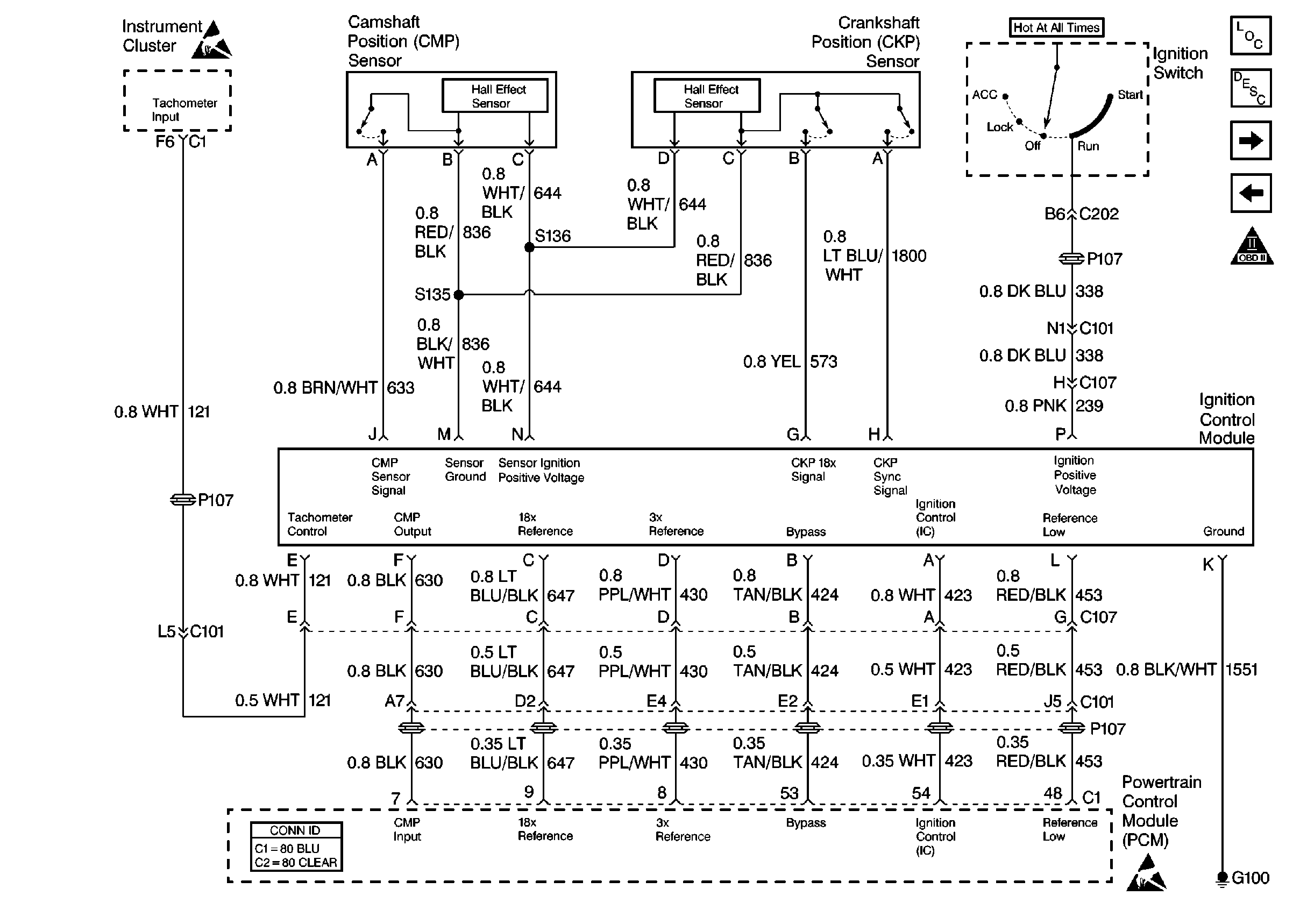
Figure 3:

Cell 20: Ignition Control Module


Object Number: 185983  Size: FS
Engine Controls Components
Powertrain Control Module Description
Cell 20: Fuel Control
Cell 20: MIL Control, DLC
OBDII Symbol Description Notice
Instrument Panel, Gages, and Console Connector End Views
Handling ESD Sensitive Parts Notice
Powertrain Control Module Connector End Views
Handling ESD Sensitive Parts Notice
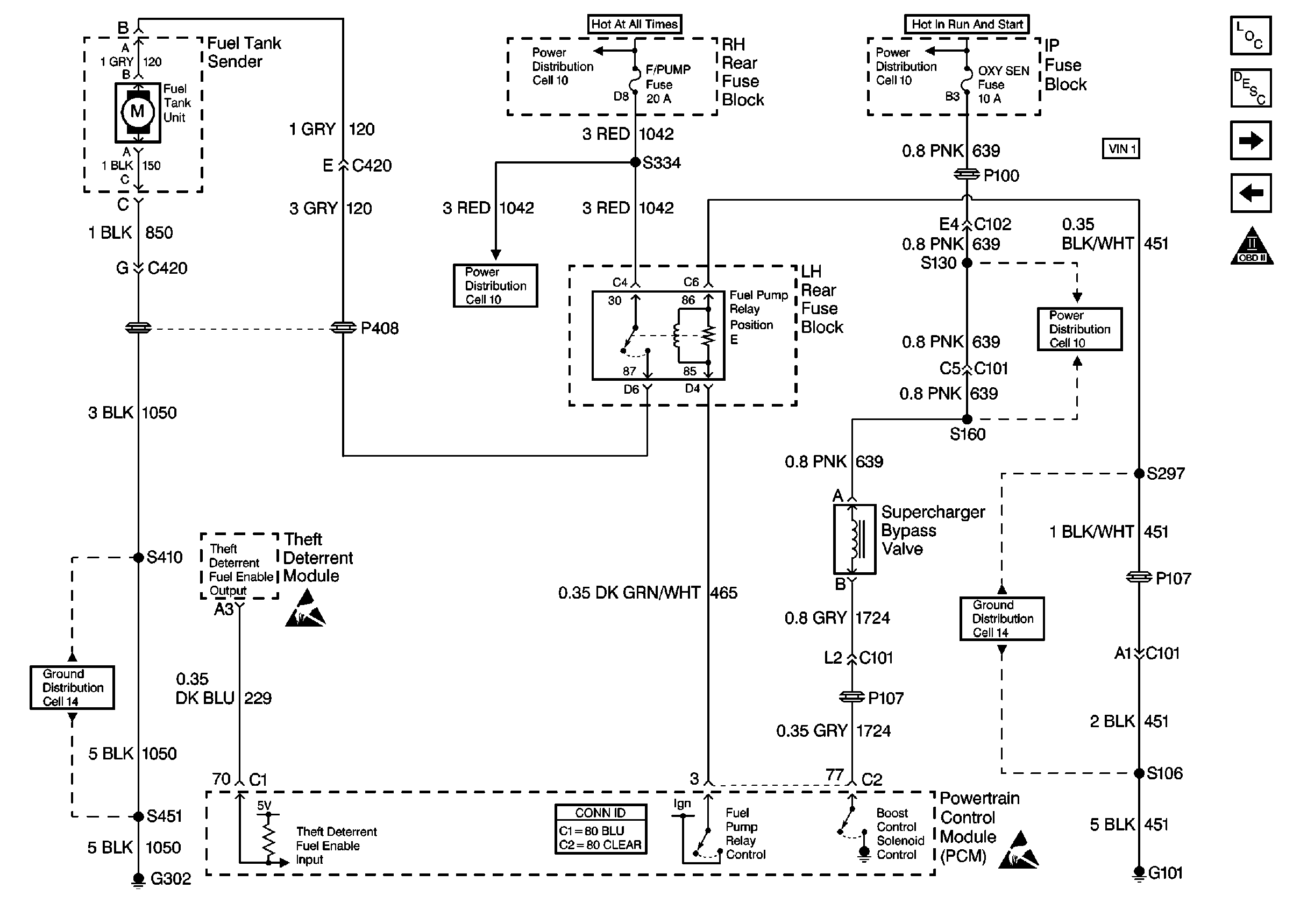
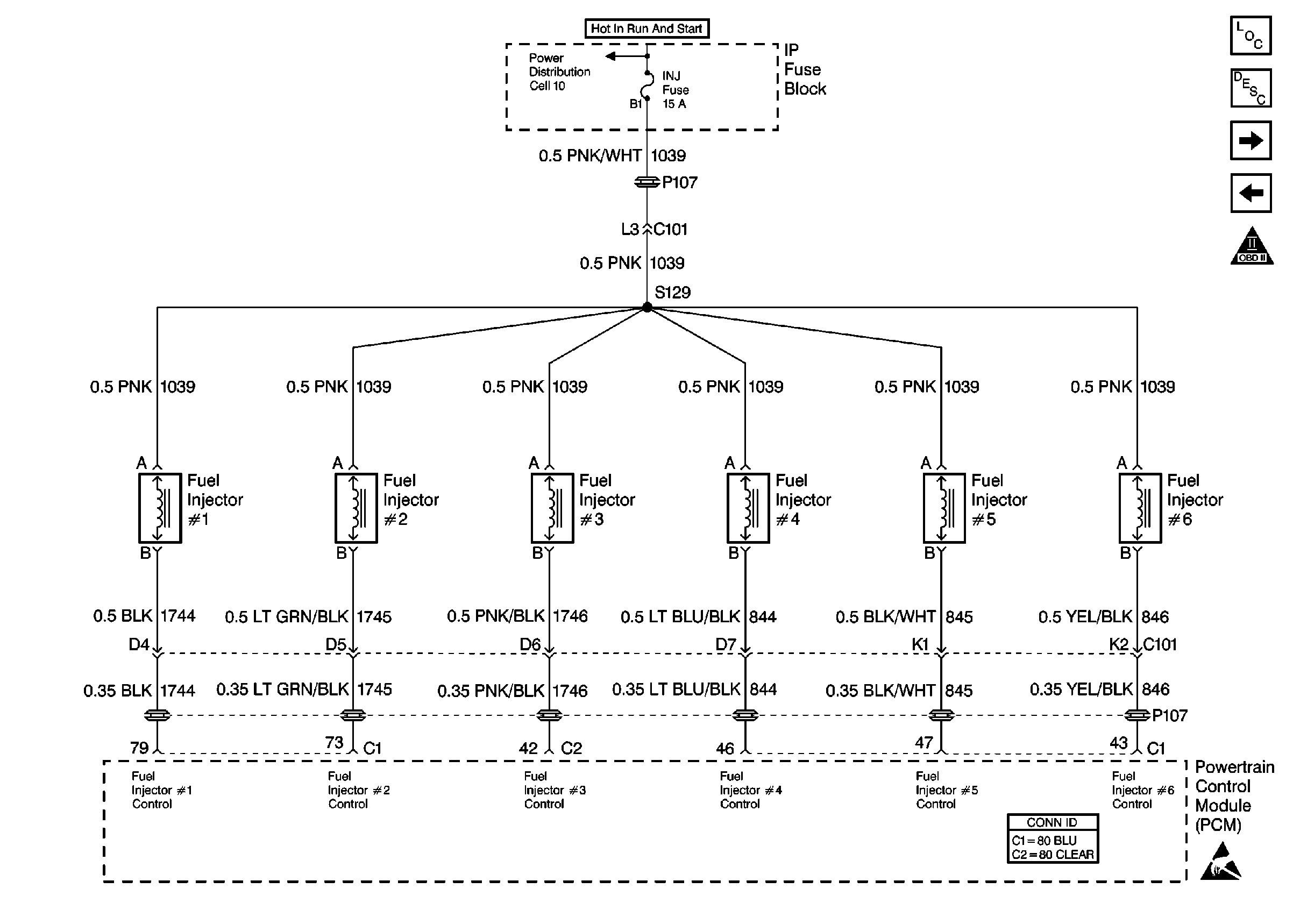
Figure 4:

Cell 20: Fuel Control


Object Number: 185989  Size: FS
Engine Controls Components
Powertrain Control Module Description
Cell 20: Fuel Injectors
Cell 20: Ignition Control Module
OBDII Symbol Description Notice
Power Distribution Schematics
Handling ESD Sensitive Parts Notice
Ground Distribution Schematics
Powertrain Control Module Connector End Views
Handling ESD Sensitive Parts Notice
Figure 5:

Cell 20: Fuel Injectors


Object Number: 185992  Size: FS
Engine Controls Components
Powertrain Control Module Description
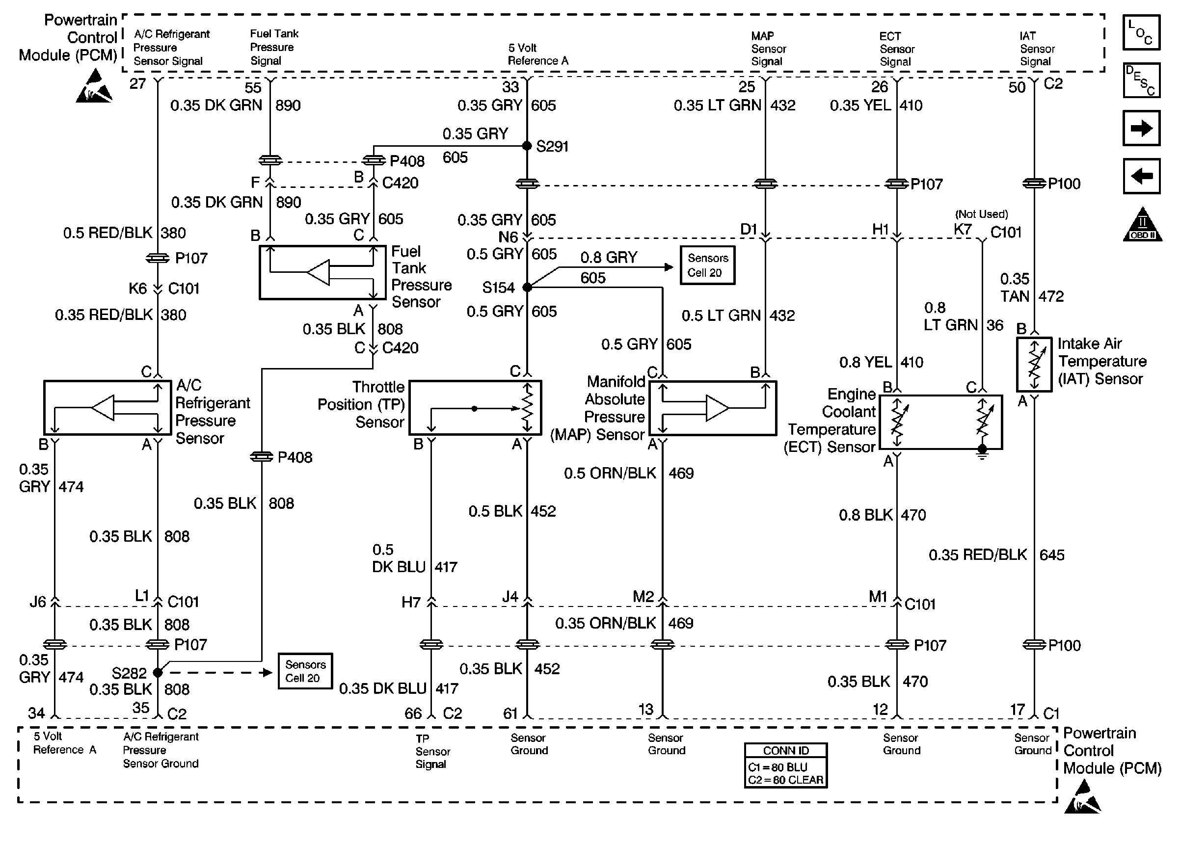
Cell 20: Sensors
Cell 20: Fuel Control
OBDII Symbol Description Notice
Power Distribution Schematics
Powertrain Control Module Connector End Views
Handling ESD Sensitive Parts Notice
Figure 6:

Cell 20: Sensors


Object Number: 185993  Size: FS
Engine Controls Components
Powertrain Control Module Description
Cell 20: EVAP Control, EGR Valve
Cell 20: Fuel Injectors
OBDII Symbol Description Notice
Handling ESD Sensitive Parts Notice
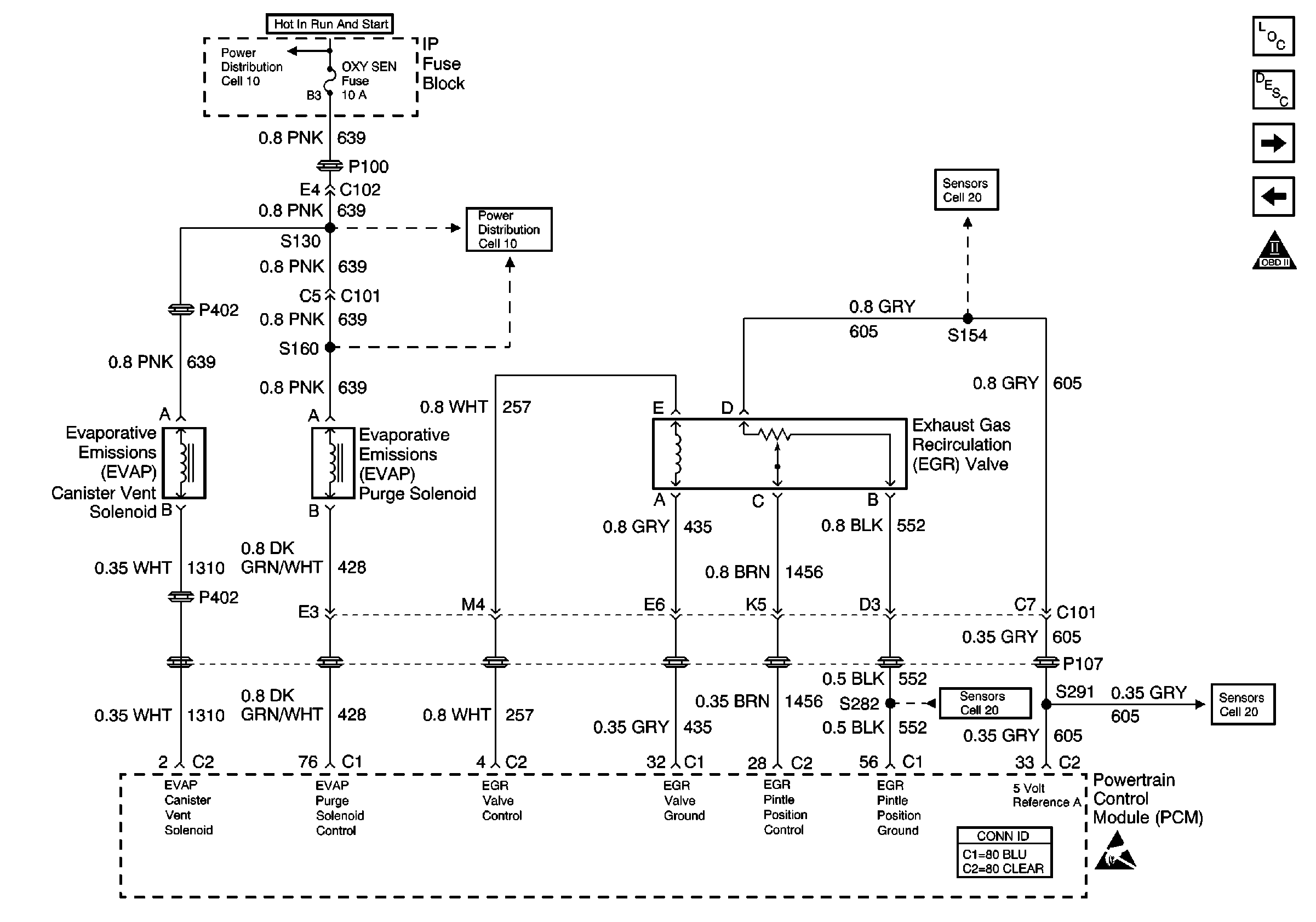
Cell 20: EVAP Control, EGR Valve
Cell 20: Transaxle - Sensors and TR Switch
Powertrain Control Module Connector End Views
Handling ESD Sensitive Parts Notice
Figure 7:

Cell 20: EVAP Control, EGR Valve


Object Number: 185994  Size: FS
Engine Controls Components
Powertrain Control Module Description
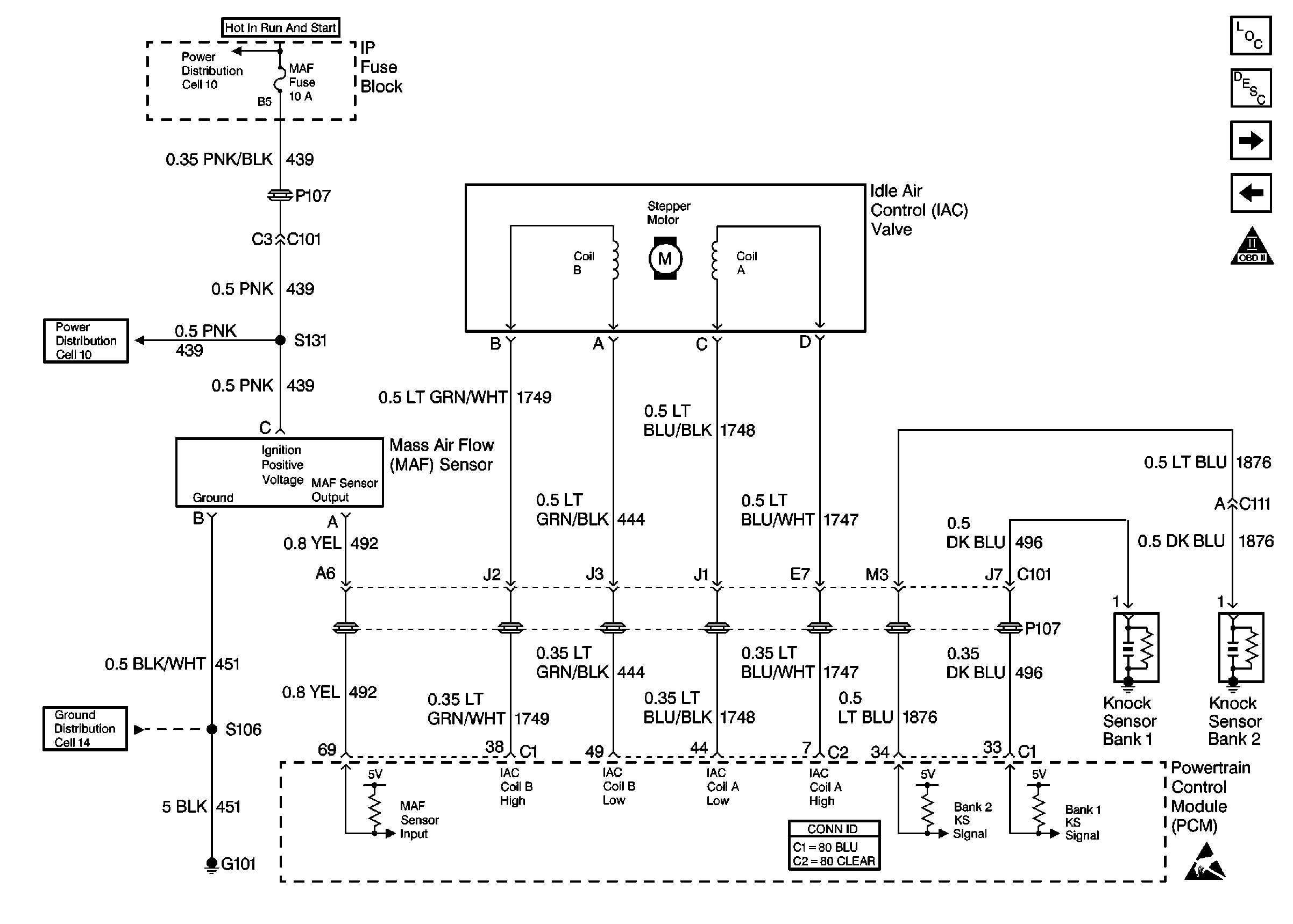
Cell 20: MAF, IAC, Knock Sensors
Cell 20: Sensors
OBDII Symbol Description Notice
Power Distribution Schematics
Cell 20: Sensors
Cell 20: Sensors
Cell 20: Sensors
Powertrain Control Module Connector End Views
Handling ESD Sensitive Parts Notice
Figure 8:

Cell 20: MAF, IAC, Knock Sensors


Object Number: 185998  Size: FS
Engine Controls Components
Powertrain Control Module Description
Cell 20: Heated Oxygen Sensors
Cell 20: EVAP Control, EGR Valve
OBDII Symbol Description Notice
Power Distribution Schematics
Ground Distribution Schematics
Powertrain Control Module Connector End Views
Handling ESD Sensitive Parts Notice
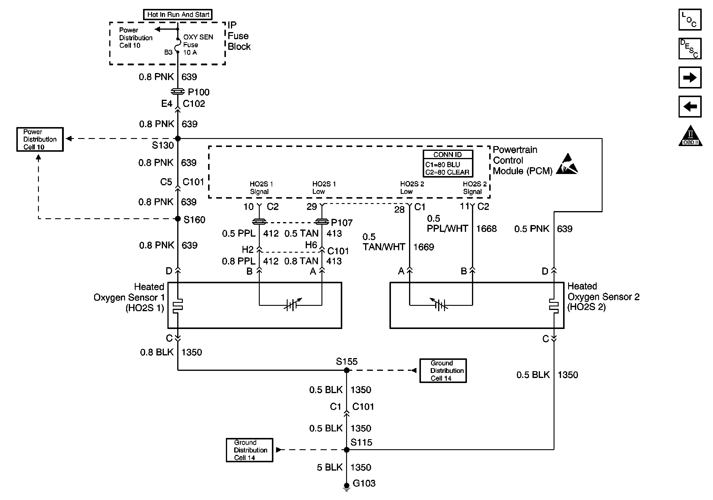
Figure 9:

Cell 20: Heated Oxygen Sensors


Object Number: 186003  Size: FS
Engine Controls Components
Powertrain Control Module Description
Cell 20: Cruise Control Module
Cell 20: MAF, IAC, Knock Sensors
OBDII Symbol Description Notice
Power Distribution Schematics
Powertrain Control Module Connector End Views
Handling ESD Sensitive Parts Notice
Ground Distribution Schematics
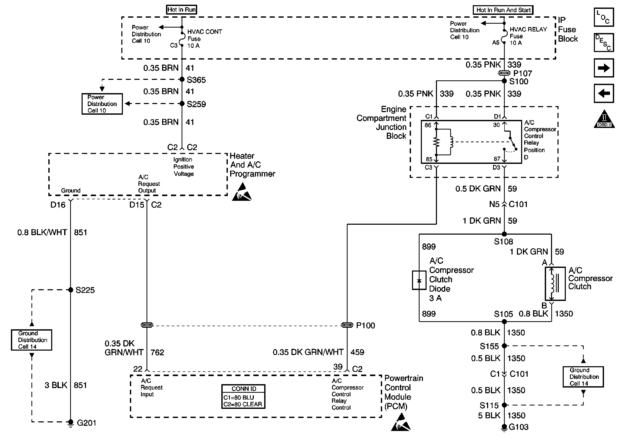
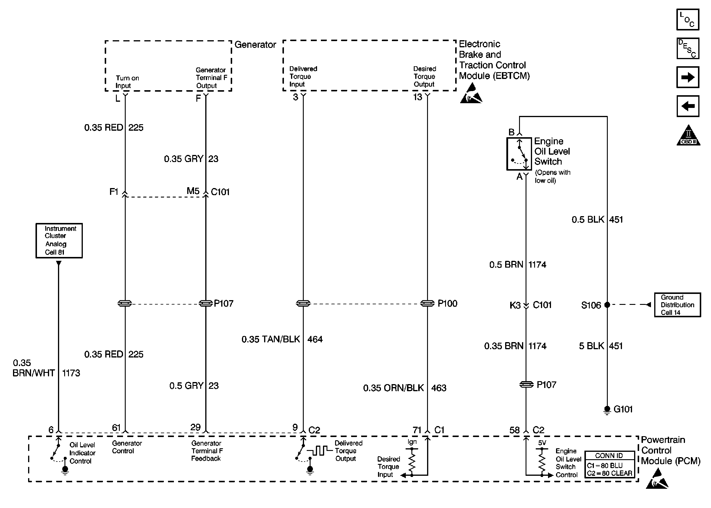
Figure 10:

Cell 20: A/C Compressor Control


Object Number: 186018  Size: FS
Engine Controls Components
Powertrain Control Module Description
Cell 20: Cooling Fans
Cell 20: Generator, Oil Level Switch, EBTCM
OBDII Symbol Description Notice
Power Distribution Schematics
Handling ESD Sensitive Parts Notice
Ground Distribution Schematics
Powertrain Control Module Connector End Views
Handling ESD Sensitive Parts Notice
Ground Distribution Schematics
HVAC Connector End Views
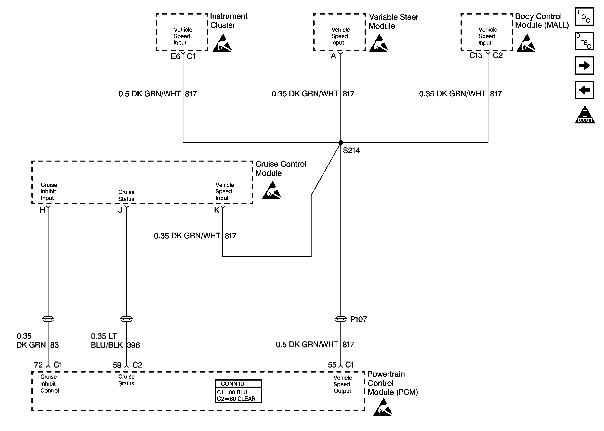
Figure 11:

Cell 20: Cruise Control Module


Object Number: 186008  Size: FS
Engine Controls Components
Powertrain Control Module Description
Cell 20: Generator, Oil Level Switch, EBTCM
Cell 20: Heated Oxygen Sensors
OBDII Symbol Description Notice
Instrument Panel, Gages, and Console Connector End Views
Body Control Module Components
Handling ESD Sensitive Parts Notice
Powertrain Control Module Connector End Views
Handling ESD Sensitive Parts Notice
Figure 12:

Cell 20: Generator, Oil Level Switch, EBTCM


Object Number: 186012  Size: FS
Engine Controls Components
Powertrain Control Module Description
Cell 20: A/C Compressor Control
Cell 20: Cruise Control Module
OBDII Symbol Description Notice
Handling ESD Sensitive Parts Notice
Engine Controls Schematic References
Ground Distribution Schematics
Powertrain Control Module Connector End Views
Handling ESD Sensitive Parts Notice
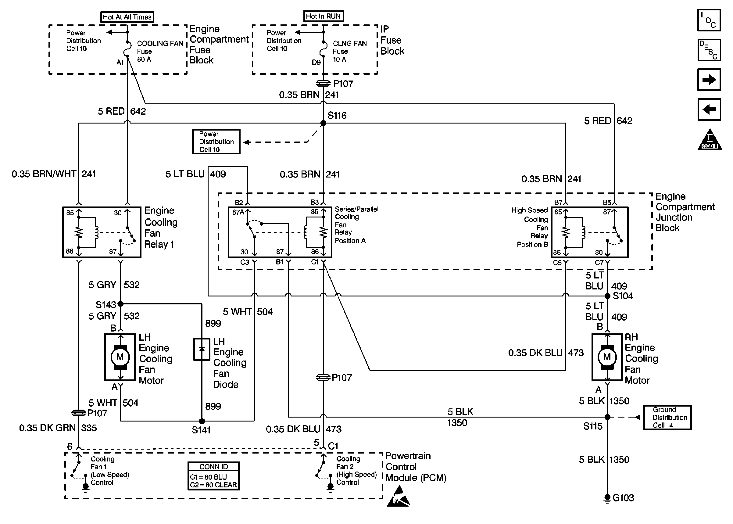
Figure 13:

Cell 20: Cooling Fans


Object Number: 186019  Size: FS
Engine Controls Components
Powertrain Control Module Description
Cell 20: TCC Switch, Transaxle Solenoids
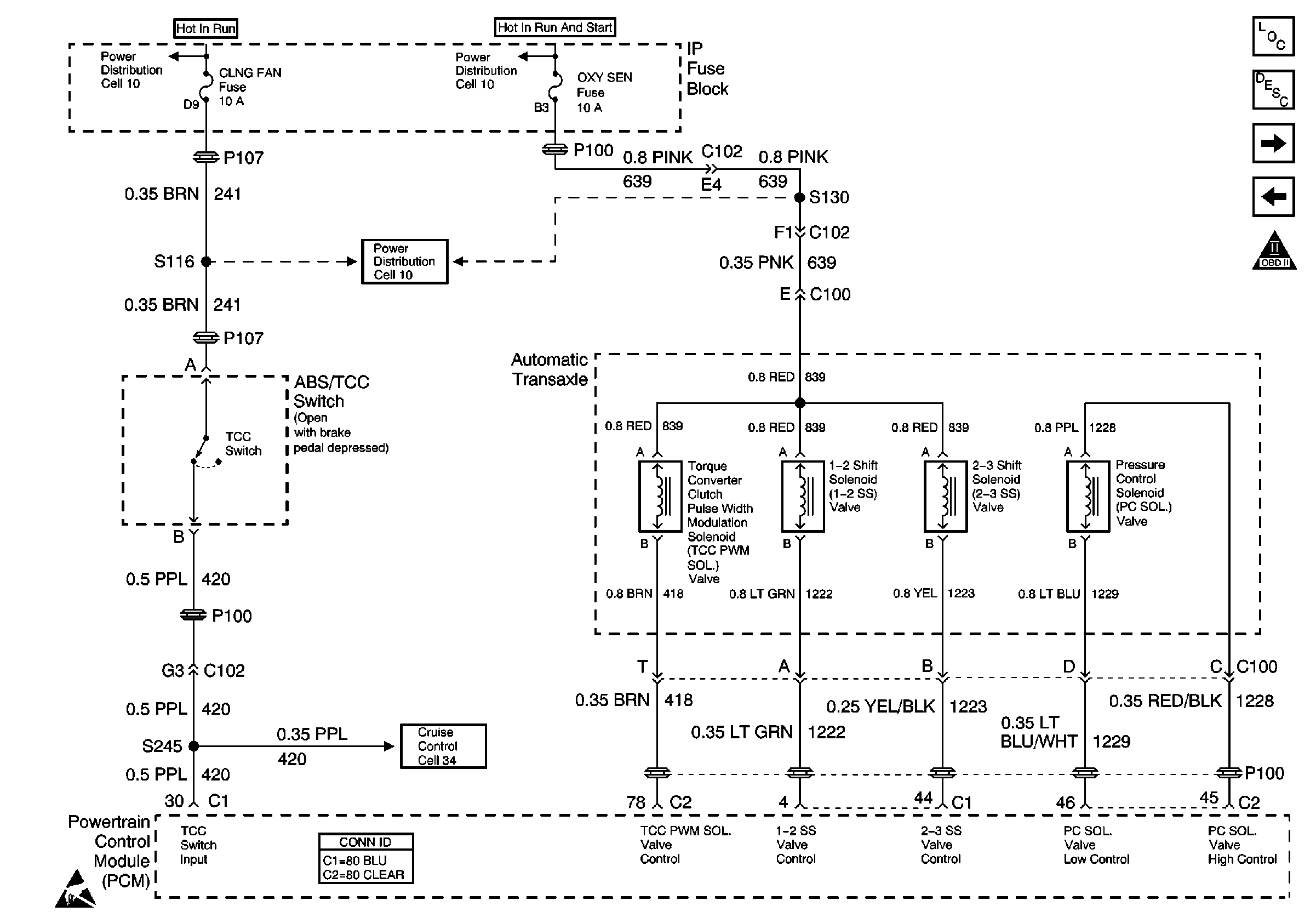
Cell 20: A/C Compressor Control
OBDII Symbol Description Notice
Power Distribution Schematics
Powertrain Control Module Connector End Views
Handling ESD Sensitive Parts Notice
Ground Distribution Schematics
Figure 14:

Cell 20: TCC Switch, Transaxle Solenoids


Object Number: 186021  Size: FS
Engine Controls Components
Powertrain Control Module Description
Cell 20: Transaxle - Sensors and TR Switch
Cell 20: Cooling Fans
OBDII Symbol Description Notice
Power Distribution Schematics
Cruise Control Schematics
Handling ESD Sensitive Parts Notice
Powertrain Control Module Connector End Views
Figure 15:

Cell 20: Transaxle -- Sensors and TR Switch
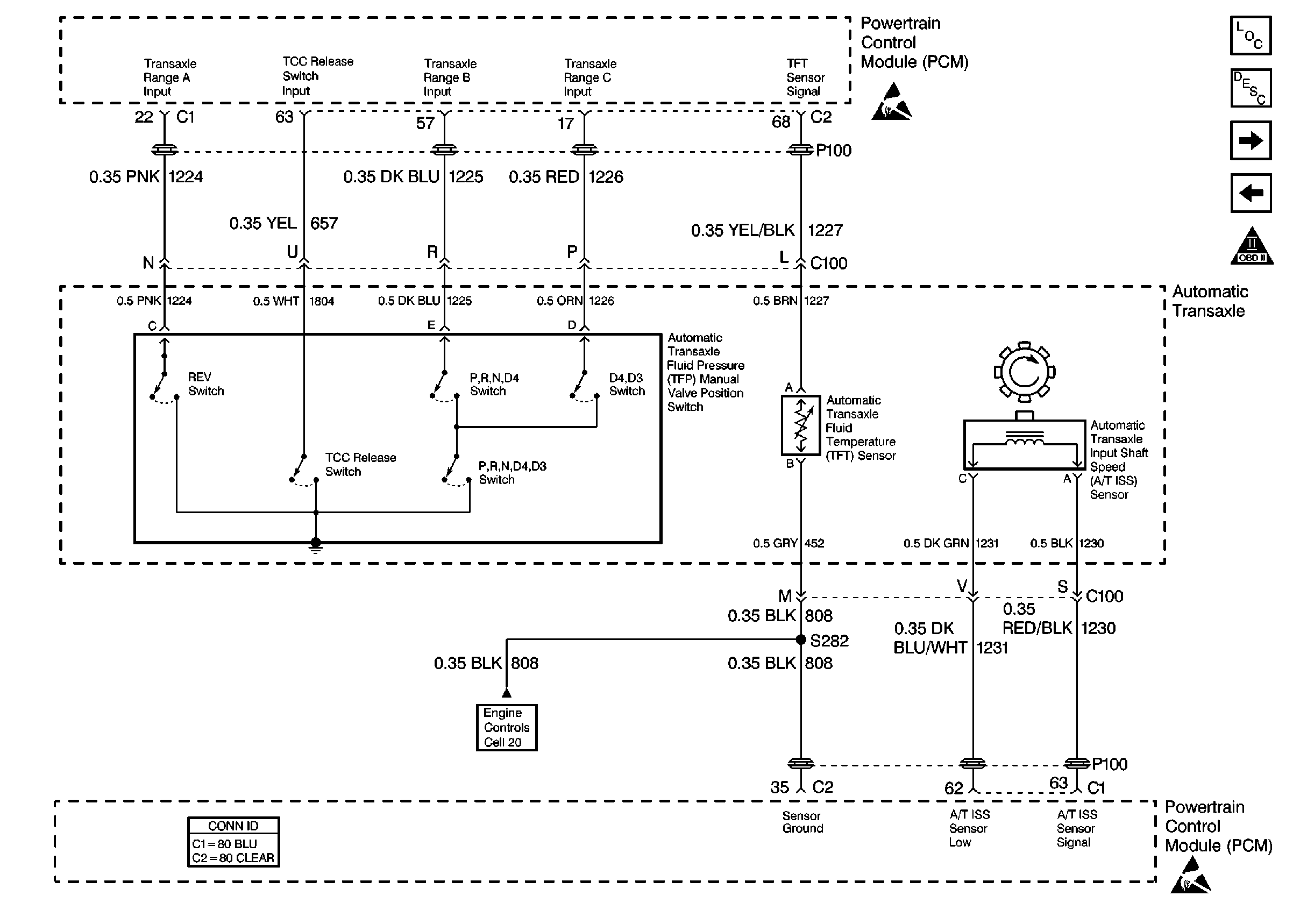

Object Number: 186024  Size: FS
Engine Controls Components
Powertrain Control Module Description
Cell 20: Park/Neutral Position (PNP) Switch
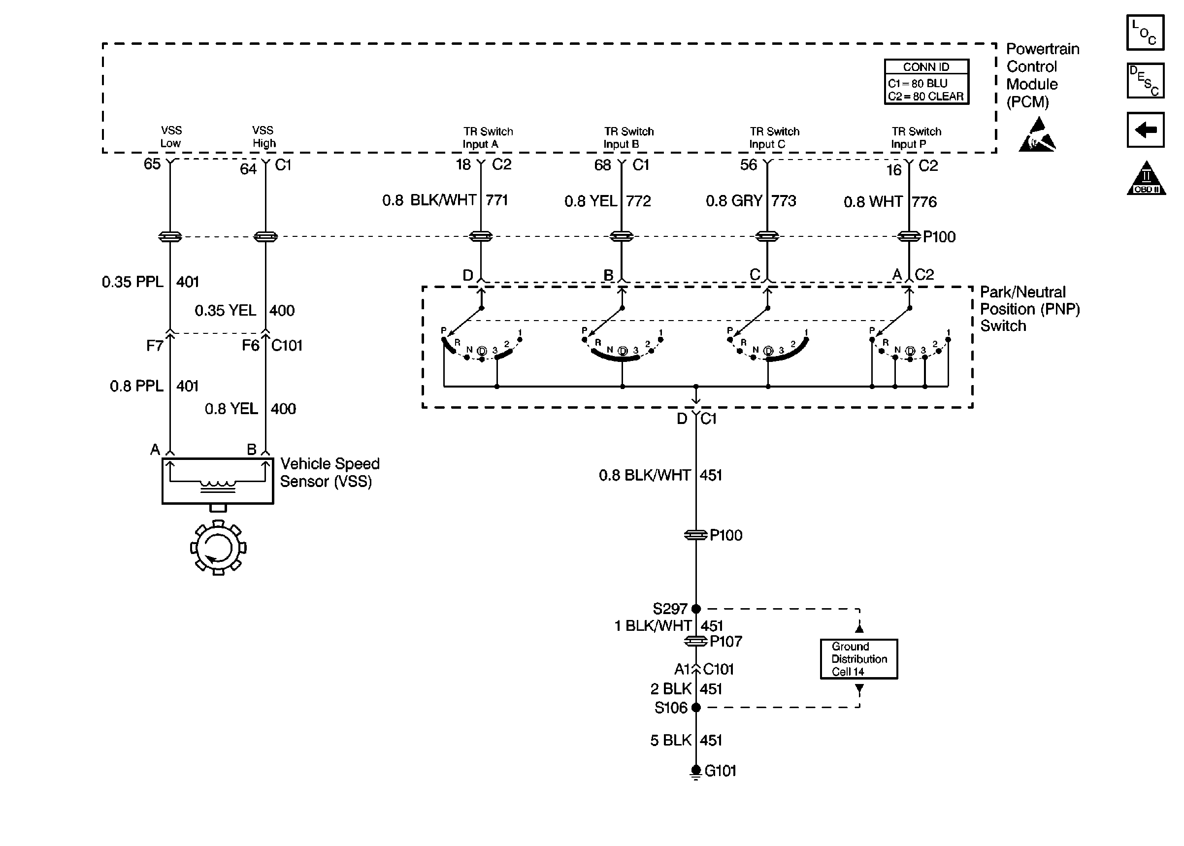
Cell 20: TCC Switch, Transaxle Solenoids
OBDII Symbol Description Notice
Handling ESD Sensitive Parts Notice
Cell 20: Sensors
Powertrain Control Module Connector End Views
Handling ESD Sensitive Parts Notice
Figure 16:

Cell 20: Park/Neutral Position (PNP) Switch


Object Number: 186029  Size: FS
Engine Controls Components
Powertrain Control Module Description
Cell 20: Transaxle - Sensors and TR Switch
OBDII Symbol Description Notice
Powertrain Control Module Connector End Views
Automatic Transmission Components
Handling ESD Sensitive Parts Notice
Ground Distribution Schematics