For 1990-2009 cars only
Removal Procedure
Tools Required
J 34730 Fuel Pressure Gauge
Caution: Provide proper ventilation when working with fuel in enclosed areas where fuel vapors can collect. The lack of adequate ventilation may result in personal injury.
Caution: Always wear safety goggles when working with fuel in order to protect the eyes from fuel splash.
Notice: Do Not handle the fuel sender assembly by the fuel pipes. The amount of leverage generated by handling the fuel pipes could damage the joints.
- Relieve the fuel system fuel pressure. Refer to Fuel Pressure Relief .
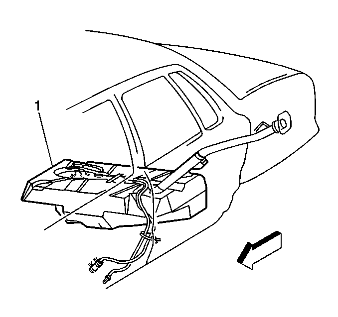
- Drain the fuel tank (1) to at least 3/4 of a tank full. Refer to Fuel Tank Draining .
- Remove the fuel sender assembly. Refer to Fuel Sender Assembly Replacement .
Important: The modular fuel sender support assembly will spring-up when the locking ring is moved.
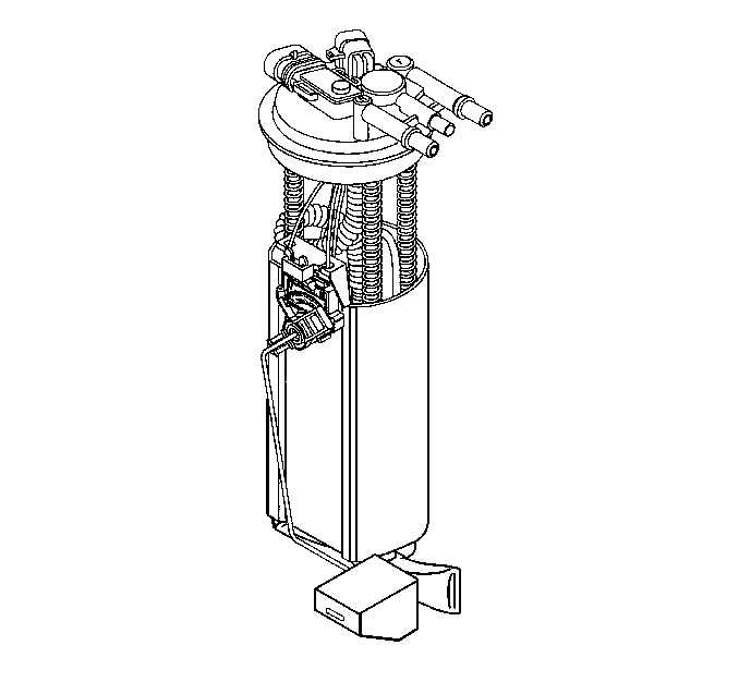
Disassemble Procedure
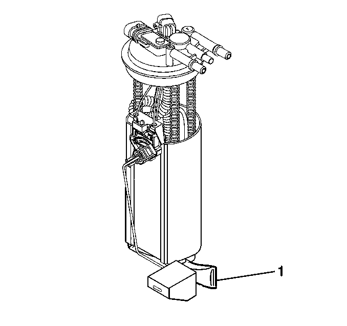
- Note the position of the fuel sender strainer (1) for installation.
- Support the reservoir with one hand and grasp the fuel sender strainer with the other hand.
- Pull the external fuel sender strainer off of the fuel pump.
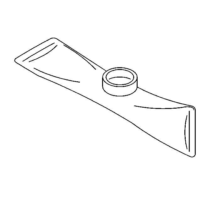
- Inspect the fuel sender strainer. If the fuel sender strainer is contaminated, the fuel tank should be cleaned.
- Discard the fuel sender strainer after inspection.
- Disassemble the electrical connectors from the sensor assembly of the fuel pump and the cover assembly.
- Disassemble the fuel level sensor assembly.
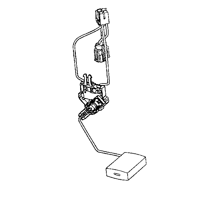
Assemble Procedure
- Assemble the fuel level sensor assembly.
- Assemble the electrical connectors to the fuel pump and the cover assembly.
- Position the new fuel sender strainer on the modular fuel sender and push on the outer edge of the fuel sender strainer until the fuel sender strainer is fully seated.


Installation Procedure
- Install the fuel sender assembly. Refer to Fuel Sender Assembly Replacement .
- Add fuel and install the fuel tank filler pipe cap.
- Install the negative battery cable. Refer to Battery Cable in Engine Electrical.
- Install the rear seat cushion. Refer to Rear Seat Cushion Replacement in Body and Accessories.

| 3.1. | Turn the ignition switch to the ON position for 2 seconds. |
| 3.2. | Turn the ignition switch to the OFF position for 10 seconds. |
| 3.3. | Turn the ignition switch to the ON position. |
| 3.4. | Visually inspect the fuel system for fuel leaks. |
