Product Safety - Rear Liftgate Latch Assembly

| Subject: | 03030B - Rear Liftgate Latch Assembly |
| Models: | 2002-2004 Buick Rendezvous |
THIS BULLETIN IS BEING REVISED TO INCLUDE ALL 2003 VEHICLES AND CERTAIN 2004 VEHICLES. DISCARD ALL COPIES OF BULLETIN 03030A, DATED OCTOBER 2003.
Condition
General Motors has decided that a defect which relates to motor vehicle safety exists in all 2002-2003 model year and certain 2004 model year Buick Rendezvous model vehicles. These vehicles were manufactured with a structural support at the latch attachment in the rear liftgate that may be inadequate to retain the latch to the liftgate in certain severe vehicle crash events. If the liftgate were open in a vehicle crash, an occupant could be ejected from the vehicle resulting in increased risk of personal injury.
Correction
Dealers are to add structural reinforcements to the liftgate in the area adjoining the latch assembly.
Vehicles Involved
Involved are all 2002-2003 model year and certain 2004 model year Buick Rendezvous vehicles built within these VIN breakpoints:
Year | Division | Model | From | Through |
|---|---|---|---|---|
2002 | Buick | Rendezvous | 2S500001 | 2S609116 |
2003 | Buick | Rendezvous | 3S500011 | 3S610198 |
2004 | Buick | Rendezvous | 4S500001 | 4S578451 |
Important: Dealers should confirm vehicle eligibility through GMVIS (GM Vehicle Inquiry System) prior to beginning recall repairs. [Not all vehicles within the above breakpoints may be involved.]
For US
For dealers with involved vehicles, a Campaign Initiation Detail Report containing the complete Vehicle Identification Number, customer name and address data has been prepared and will be loaded to the GM DealerWorld, Recall Information website. Dealers that have no involved vehicles currently assigned will not have a report available in GM DealerWorld.
For Canada & IPC
For dealers with involved vehicles, a Campaign Initiation Detail Report containing the complete Vehicle Identification Number, customer name and address data has been prepared and is being furnished to involved dealers. Dealers that have no involved vehicles currently assigned will not receive a report with the recall bulletin.
The Campaign Initiation Detail Report may contain customer names and addresses obtained from Motor Vehicle Registration Records. The use of such motor vehicle registration data for any purpose other than follow-up necessary to complete this recall is a violation of law in several states/provinces/countries. Accordingly, you are urged to limit the use of this report to the follow-up necessary to complete this recall.
Parts Information
Parts Pre-Ship Information - For US and Canada
Important: An initial supply of liftgate lock kits required to complete this program will be pre-shipped to involved dealers of record. This pre-shipment is scheduled to begin the week of June 7, 2004 and will be approximately 20% of each dealer's involved vehicles. Pre-shipped parts will be charged to dealer's open parts account.
Additional parts, if required, are to be obtained from General Motors Service Parts Operations (GMSPO). Please refer to your "involved vehicles listing" before ordering parts. Normal orders should be placed on a DRO=Daily Replenishment Order. In an emergency situation, parts should be ordered on a CSO=Customer Special Order.
Part Number | Description | Qty |
|---|---|---|
10351118 | L/Gate Lock Kit | 1 |
Service Procedure
The following service procedure provides instructions for installing reinforcements to the rear liftgate and latch. All parts necessary to perform the installation are included in the kit. For additional information on trim removal, refer to the Body and Accessories section of the appropriate Service Manual or SI.
Tools Required
J 38778 Door Trim Pad and Garnish Clip Remover
Important: Read the complete service procedure before beginning the repair.
Before beginning, open the liftgate lock kit and review the contents.| • | (1) Outer Metal Strap |
| • | (1) Inner Metal "Z" Strap |
| • | (6) Rivets |
| • | (3) Replacement Latch Screws |
| • | (2) Bolts |
| • | (1) Striker Shim |
- Open the rear liftgate.
- Release the four latches that secure the access trim panel to the inside of the liftgate, and remove the panel.
- On vehicles equipped with an inside pull strap, remove the two screws that attach it to the liftgate.
- On vehicles equipped with a "pocket" on the bottom edge of the interior trim panel, remove the two screws at the opening.
- Release the retaining clips that attach the bottom section interior trim panel to the liftgate and partially lower the panel.
- Remove the small clear plastic water deflector that covers the opening in the liftgate for latch access.
- Remove the three TORX® head screws that attach the latch to the liftgate and discard the screws.
- Remove the latch from the liftgate and disconnect the electrical connection.
- Remove the nine screws that attach the liftgate lower molding to the exterior of the liftgate.
- Carefully release the retainers that attach the upper edge of the liftgate lower molding to the tail lamp/license plate located directly above it. Remove the molding.
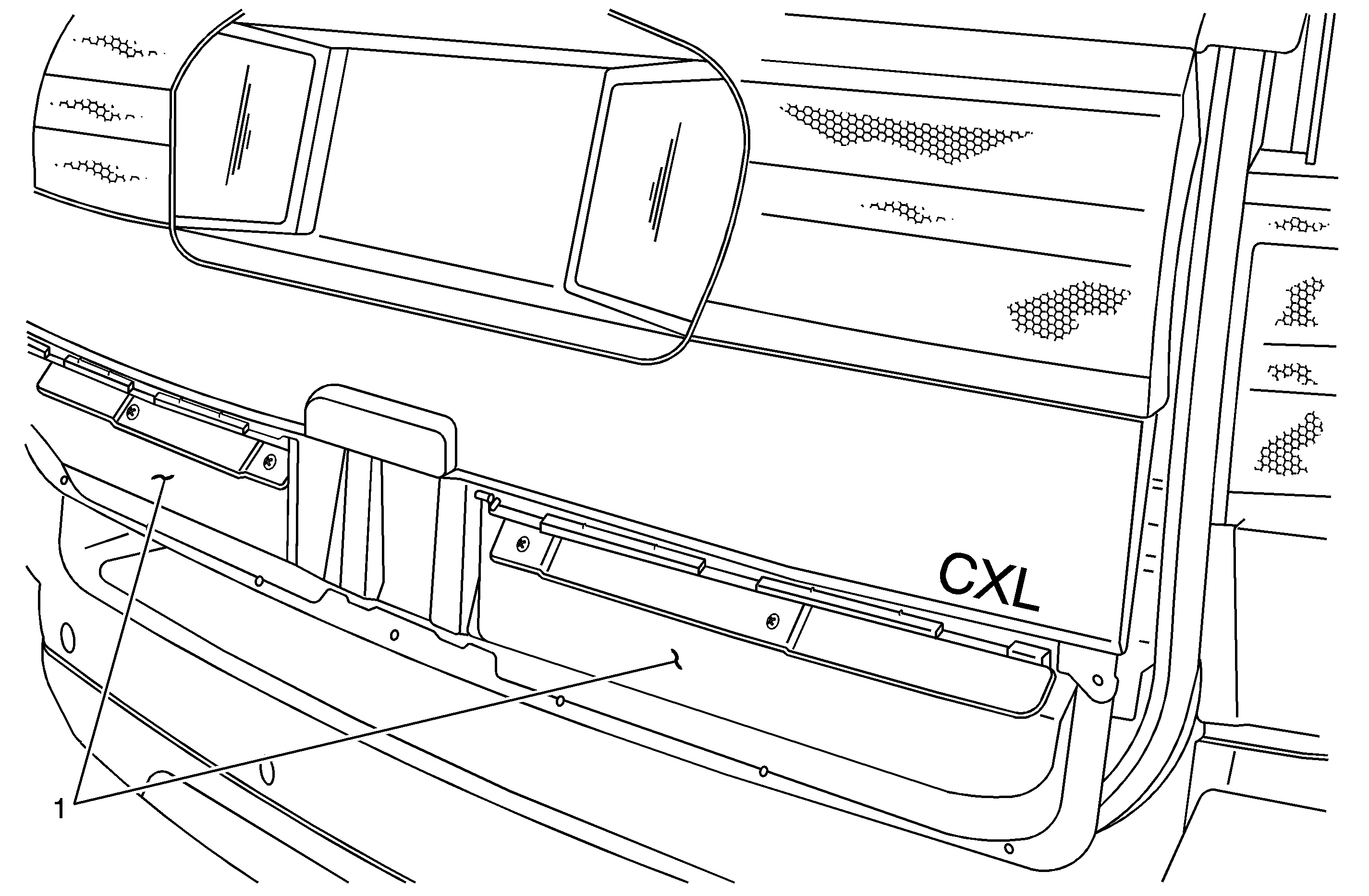
- Once the liftgate lower molding has been removed, the section (1) of the liftgate where the reinforcement is to be installed can be seen.
- Position the outer metal strap (3) to the outside of the liftgate as shown.
- While holding the outer metal strap (1) in position, mark the location of the two holes (2) in the center of the strap on the liftgate with a pencil. Remove the outer metal strap.
- Using a 5/16 inch drill bit, drill holes in the liftgate at the two locations marked in the previous step.
- Position the outer metal strap to the liftgate and hold it in place with a couple of pieces of masking tape.
- Install the inner metal "Z" strap (2) as shown inside the opening in the liftgate where the latch is located.
- While holding the "Z" strap in position, install the two bolts through the holes of the outer metal strap, the liftgate, and into the weld nuts on the "Z" strap. Align the outer metal strap to the liftgate.
- Using a pencil, mark the location of the remaining six holes in the outer metal strap.
- Using a 3/16 inch drill bit, drill holes in the liftgate at the six locations marked in the previous step.
- Beginning on the right side of the outer metal strap, and using the rivets supplied in the kit, attach the strap to the liftgate at the three drilled holes in the order listed below.
- Repeat the riveting sequence on the left side of the outer metal strap.
- Remove the masking tape.
- Connect the electrical connectors to the latch and install the assembly back inside the opening in the liftgate. Install the three new bolts supplied in the kit.
- Reposition the clear plastic water deflector over the opening.
- Remove the striker (1) for the liftgate latch from the body.
- Install the shim included in the kit between the body and the striker.
- Reinstall the bolts.
- Position the liftgate lower molding to the exterior edge of the liftgate and engage the retainers along the upper edge.
- Install the nine attaching screws along the inside bottom edge.
- Position the interior trim panel to the liftgate and engage the retaining clips.
- On vehicles equipped with an inside pull strap, position the strap to the interior trim panel and install the two screws.
- On vehicles equipped with a "pocket" on the bottom edge of the interior trim panel, install the two screws at the opening.
- Install the access trim panel to the inside of the liftgate, and secure the four latches.
- Close the liftgate and verify latch operation.
Notice: Failure to follow the next step in the exact sequence that it is written may result in damage to the interior trim panel. Read the entire step BEFORE doing anything.
Notice: Using tools other than those listed or using excessive force will damage the interior trim panel.
| Important: The illustration below shows the location of the twelve fasteners in the bottom section of the trim panel. |
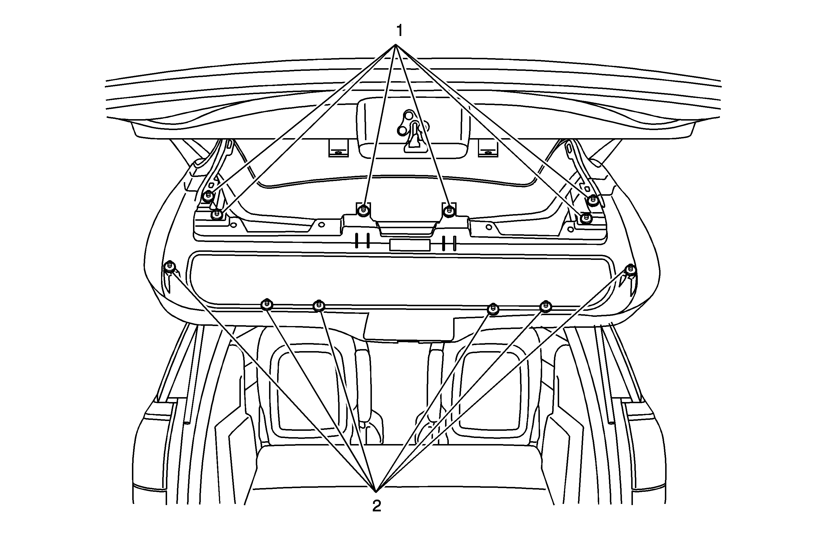
| 5.1. | There are a total of twelve fasteners, six upper (1) and six lower (2), that must be released in order to "lower" the bottom section of the interior trim panel from the liftgate. The six upper retainers (1) must be released first. |
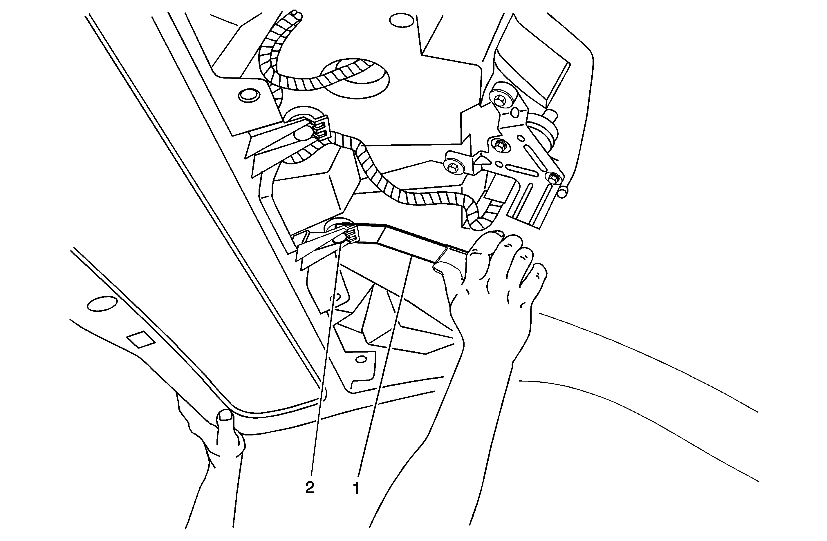
| 5.2. | Using the J 38778 (1), release the six upper retainers (2) from the liftgate. Do not attempt to release the six lower retainers until all of the upper retainers are released. |
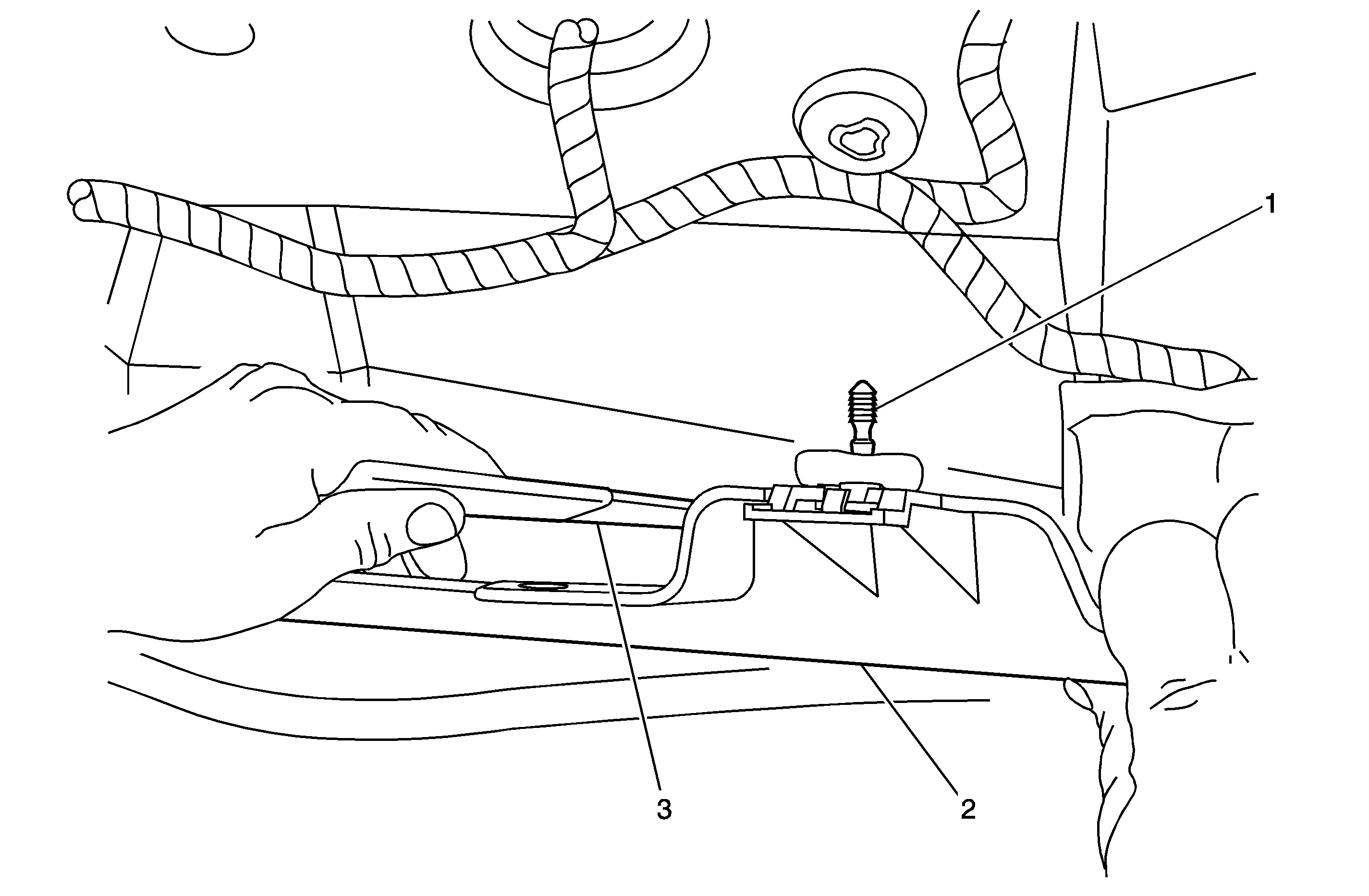
| 5.3. | Once the six upper retainers (1) have been released, the interior trim panel (2) can be slightly pulled down in the middle to improve tool (3) access to the six lower retainers located down inside the panel. |
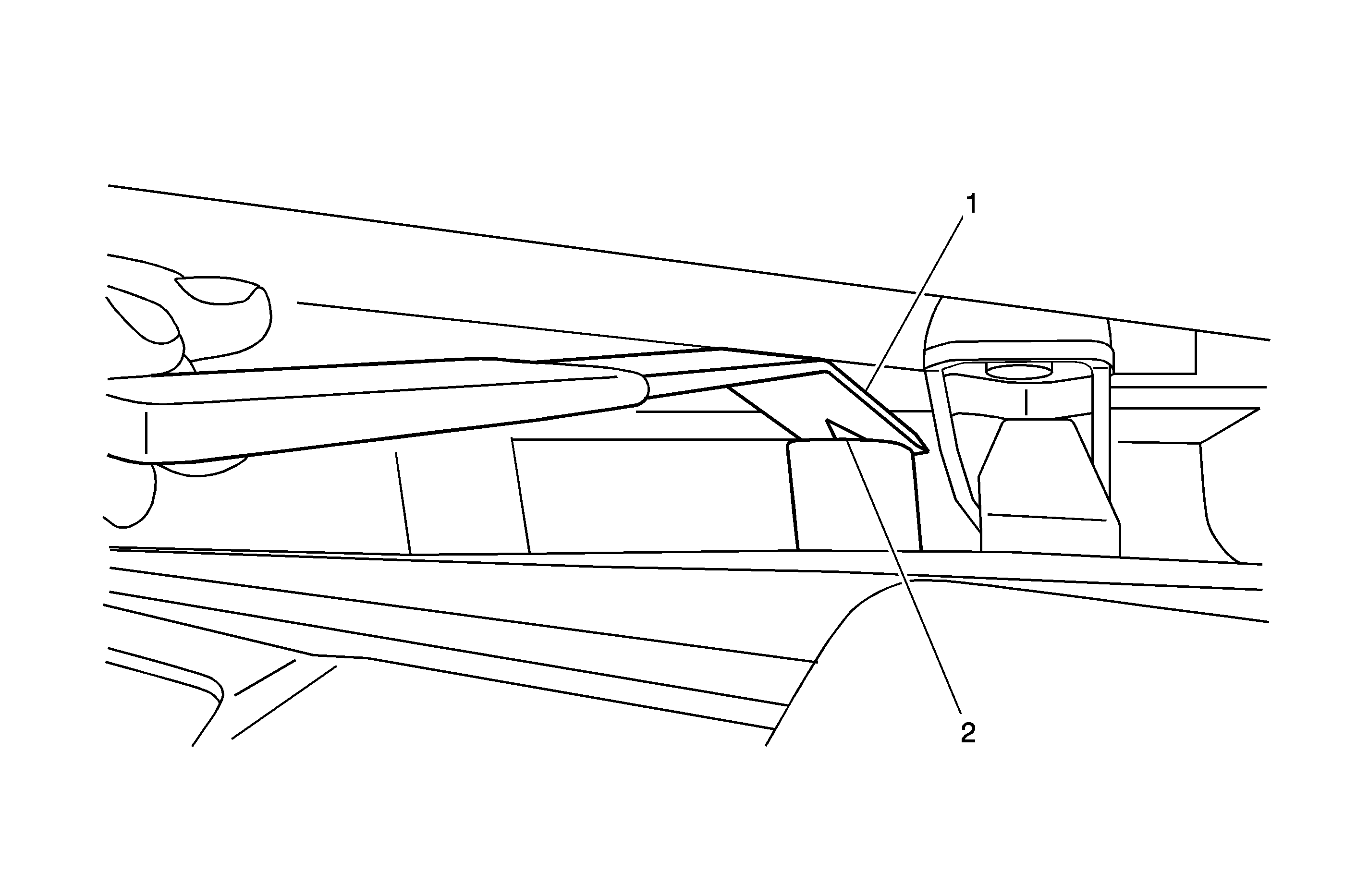
| 5.4. | Starting in the middle of the panel and working toward the outer edge, use the J 38778 (1) to release the three lower retainers (2) on the right side. Then repeat this step beginning in the middle and working toward the left side. |
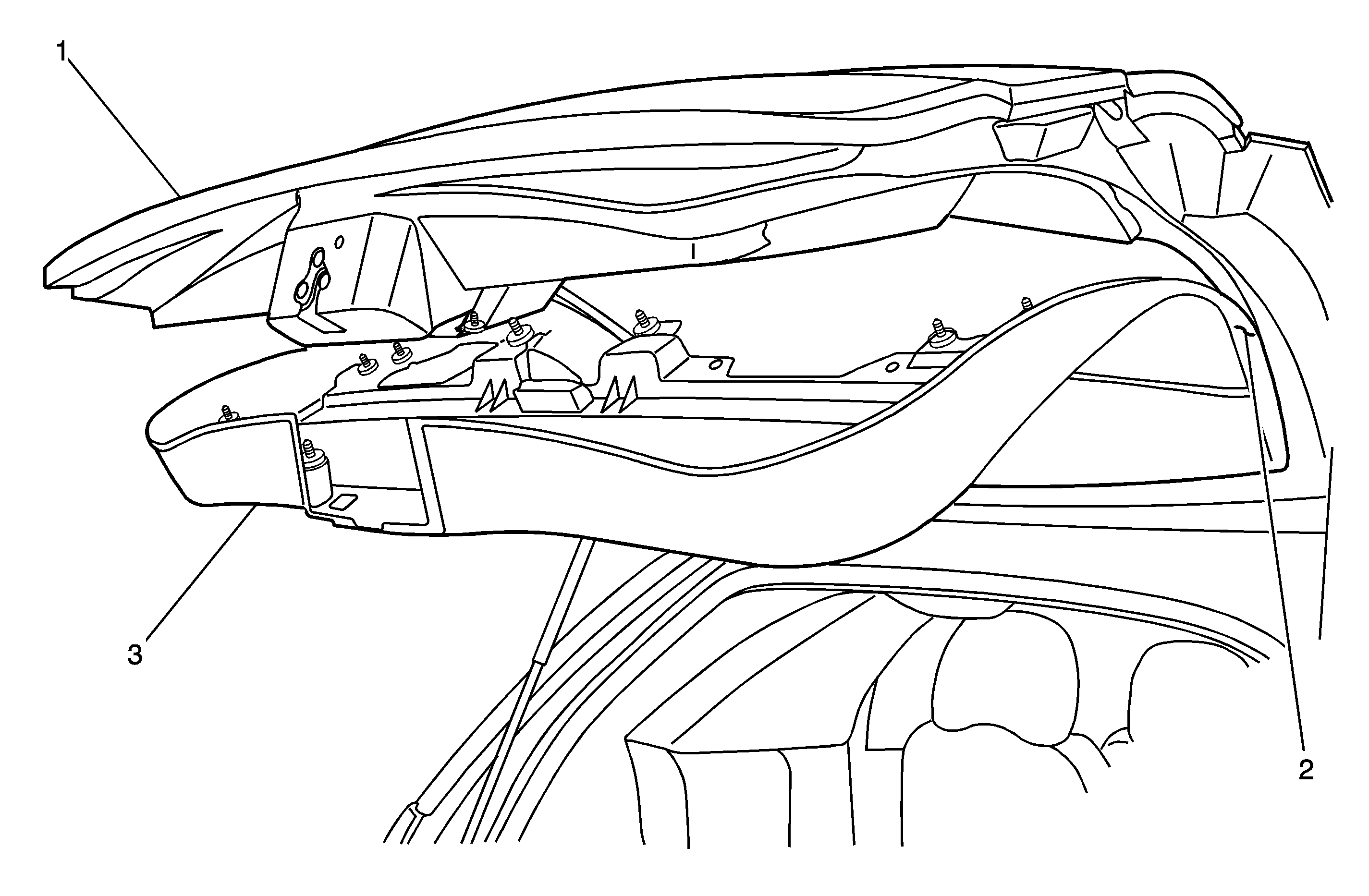
| Notice: Do not allow the interior trim to "hang" for prolonged periods (lunch, breaks, overnight, etc.) after lowering it in the next step. Support the panel to the liftgate when necessary with strips of masking tape. |
| 5.5. | Carefully lower the bottom section of the interior trim panel (3) away from the liftgate (1) to access the small clear water deflector in the next step. It is not necessary to release the retainer 92) located on each side of the liftgate glass or the retainers along the top (above the glass) of the panel. |
The nine screws can be found along the inside bottom edge of the liftgate.
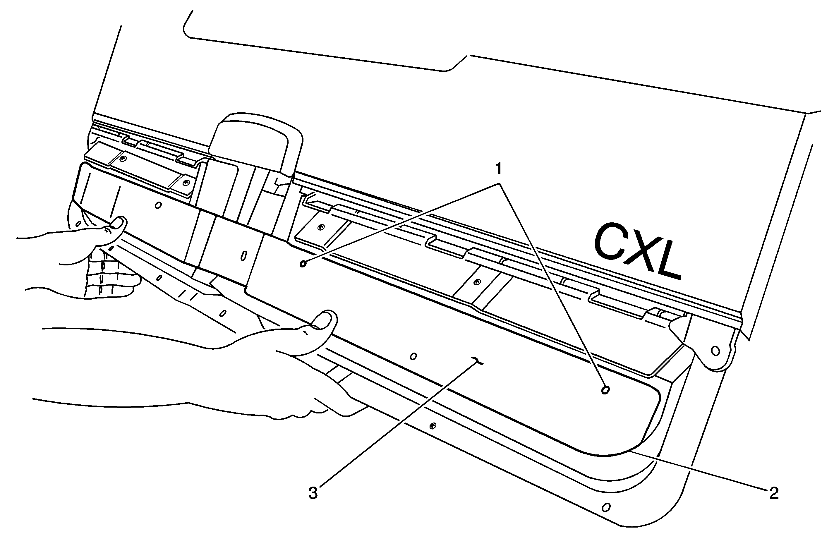
Important: When the outer metal strap (3) is properly positioned in the next step, the curved corner on each end will align with the curved corners (2) on the liftgate. In addition, two of the three small holes (1) in each side of the strap will be upward.
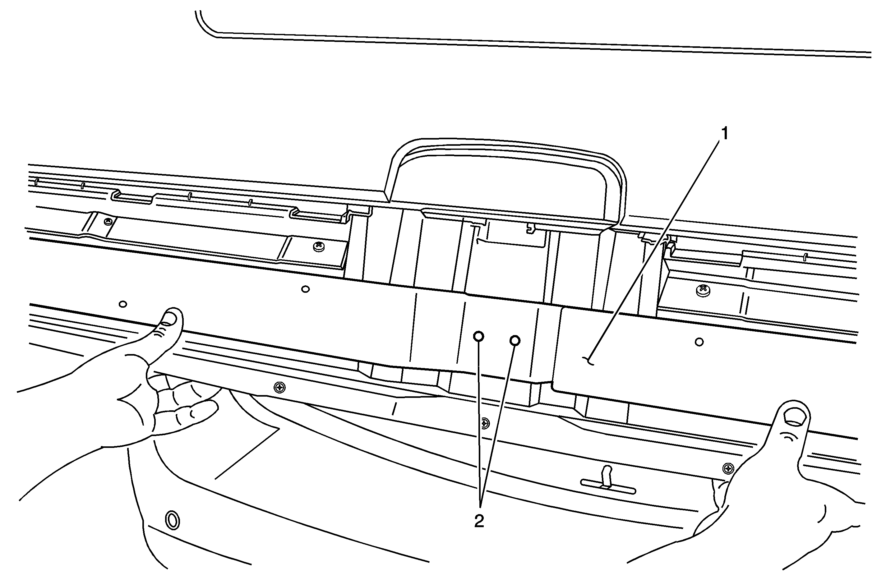
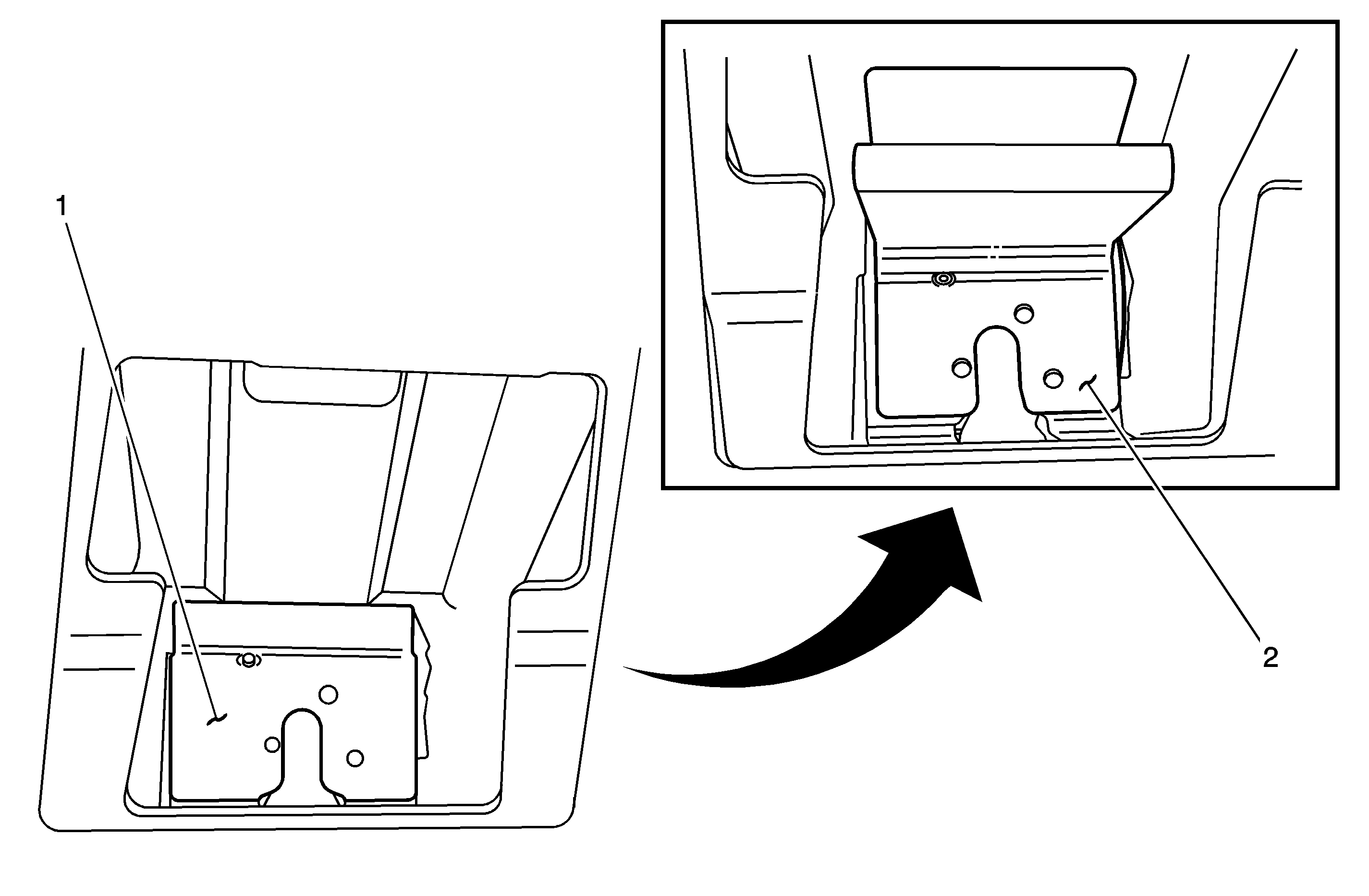
Important: The above illustration shows the inside of the liftgate with the latch removed (1) and with the inner metal "Z" strap (2) installed.
Tighten
Tighten the bolts to 10 N·m (89 lb in).
Important: Before making the holes in the next step, make sure that each section of the outer metal strap is flush to the liftgate. Starting at the center, apply pressure to the right side of the strap, working your way outwards towards the end. As you pass each hole, mark its location on the liftgate with the pencil. Repeat this procedure on the left side of the strap.
Important: A standard type rivet gun will be required for installing the rivets in the next step.
| 20.1. | Inboard rivet |
| 20.2. | Center rivet |
| 20.3. | Outboard rivet |
Tighten
Tighten the bolts to 10 N·m (89 lb in).
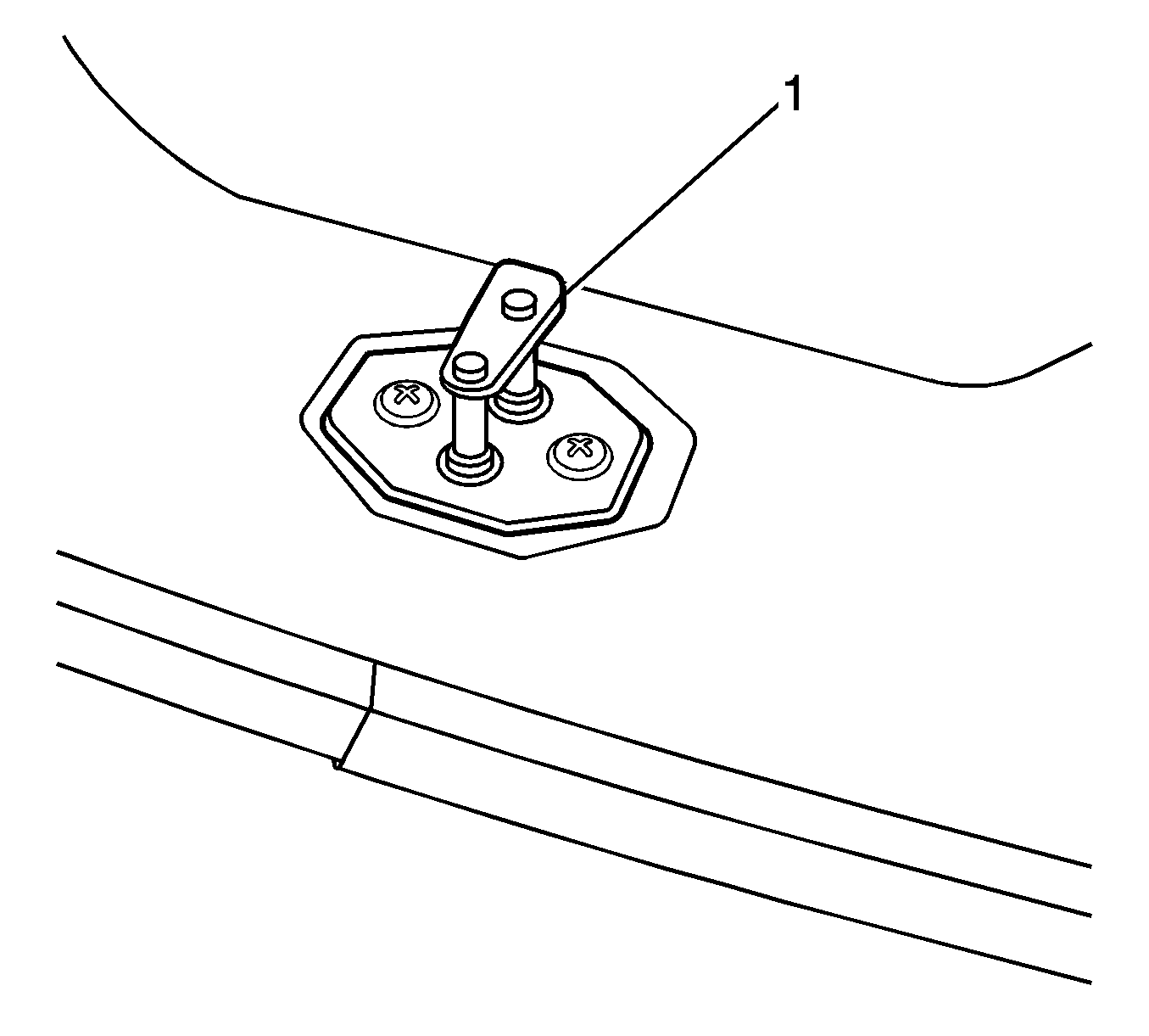
Important: The purpose of installing the shim to the striker in the next step is to compensate for the thickness of the "Z" strap installed between the latch and the liftgate.
Tighten
Tighten the bolts to 25 N·m (18 lb ft).
Tighten
Tighten the bolts to 2 N·m (18 lb in).
Tighten
Tighten the bolts to 2 N·m (18 lb in).
Tighten
Tighten the bolts to 2 N·m (18 lb in).
Courtesy Transportation
The General Motors Courtesy Transportation program is intended to minimize customer inconvenience when a vehicle requires a repair that is covered by the New Vehicle Limited Warranty. The availability of courtesy transportation to customers whose vehicles are within the warranty coverage period and involved in a product recall is very important in maintaining customer satisfaction. Dealers are to ensure that these customers understand that shuttle service or some other form of courtesy transportation is available and will be provided at no charge. Dealers should refer to the General Motors Service Policies and Procedures Manual for Courtesy Transportation guidelines.
Claim Information
Submit a Product Recall Claim with the information indicated below:
Repair Performed | Part Count | Part No. | Parts Allow | CC-FC | Labor Op | Labor Hours |
|---|---|---|---|---|---|---|
Install Liftgate Lock Kit | 1 | -- | ** | MA-96 | V1028 | 0.6* |
Courtesy Transportation | N/A | N/A | N/A | MA-96 | *** | N/A |
* -- For Program Administrative Allowance, add 0.1 hours to the "Labor Hours". ** -- The "Parts Allowance" should be the sum total of the current GMSPO Dealer net price plus applicable Mark-Up or Landed Cost Mark-Up (for IPC) for the liftgate lock kit needed to complete the repair. *** -- Submit courtesy transportation using normal labor operations for courtesy transportation as indicated in the GM Service Policies and Procedures Manual. | ||||||
Refer to the General Motors WINS Claims Processing Manual for details on Product Recall Claim Submission.
Customer Notification - For US and Canada
General Motors will notify customers of this recall on their vehicle (see copy of customer letter included with this bulletin).
Customer Notification - For IPC
Letters will be sent to known owners of record located within areas covered by the US National Traffic and Motor Vehicle Safety Act. For owners outside these areas, dealers should notify customers using the attached sample letter.
Dealer Recall Responsibility - For US and IPC (US States, Territories, and Possessions)
The US National Traffic and Motor Vehicle Safety Act provides that each vehicle which is subject to a recall of this type must be adequately repaired within a reasonable time after the customer has tendered it for repair. A failure to repair within sixty days after tender of a vehicle is prima facie evidence of failure to repair within a reasonable time. If the condition is not adequately repaired within a reasonable time, the customer may be entitled to an identical or reasonably equivalent vehicle at no charge or to a refund of the purchase price less a reasonable allowance for depreciation. To avoid having to provide these burdensome remedies, every effort must be made to promptly schedule an appointment with each customer and to repair their vehicle as soon as possible. In the recall notification letters, customers are told how to contact the US National Highway Traffic Safety Administration if the recall is not completed within a reasonable time.
Dealer Recall Responsibility - All
All unsold new vehicles in dealers' possession and subject to this recall MUST be held and inspected/repaired per the service procedure of this recall bulletin BEFORE customers take possession of these vehicles.
Dealers are to service all vehicles subject to this recall at no charge to customers, regardless of mileage, age of vehicle, or ownership, from this time forward.
Customers who have recently purchased vehicles sold from your vehicle inventory, and for which there is no customer information indicated on the dealer listing, are to be contacted by the dealer. Arrangements are to be made to make the required correction according to the instructions contained in this bulletin. This could be done by mailing to such customers a copy of the customer letter accompanying this bulletin. Recall follow-up cards should not be used for this purpose, since the customer may not as yet have received the notification letter.
In summary, whenever a vehicle subject to this recall enters your vehicle inventory, or is in your dealership for service in the future, please take the steps necessary to be sure the recall correction has been made before selling or releasing the vehicle.
June 2004Dear General Motors Customer:
This notice is sent to you in accordance with the requirements of the National Traffic and Motor Vehicle Safety Act. Federal regulation requires that any vehicle lessor receiving this recall notice must forward a copy of this notice to the lessee within ten days.
Reason For This Recall
General Motors has decided that a defect which relates to motor vehicle safety exists in all 2002 and 2003 model year and certain 2004 model year Buick Rendezvous model vehicles. These vehicles were manufactured with a structural support at the latch attachment in the rear liftgate that may be inadequate to retain the latch to the liftgate in certain severe vehicle crash events. If the liftgate were open in a vehicle crash, an occupant could be ejected from the vehicle resulting in increased risk of personal injury.
What Will Be Done
Your GM dealer will add structural reinforcements to the liftgate in the area adjoining the latch assembly. This service will be performed for you at no charge .
How Long Will The Repair Take?
This service correction will take approximately 40 minutes. However, due to service scheduling requirements, your dealer may need your vehicle for a longer period of time.
Contacting Your Dealer
To limit any possible inconvenience, we recommend that you contact your GM dealer as soon as possible to schedule an appointment for this repair. By scheduling an appointment, your dealer can ensure that the necessary parts will be available on your scheduled appointment date. Should your dealer be unable to schedule a service date within a reasonable time, you should contact the appropriate Customer Assistance Center at the listed number below. The Customer Assistance Centers hours of operations are 8:00 AM - 11:00 PM, EST, Monday through Friday.
Division | Number | Text Telephone (TTY) |
|---|---|---|
Buick | 1-800-608-8080 | 1-800-832-8425 |
Puerto Rico - English | 1-800-496-9992 |
|
Puerto Rico - Español | 1-800-496-9993 |
|
Virgin Islands | 1-800-496-9994 |
|
If, after contacting the appropriate customer assistance center, you are still not satisfied that we have done our best to remedy this condition without charge and within a reasonable time, you may wish to write the Administrator, National Highway Traffic Safety Administration, 400 Seventh Street SW, Washington, DC 20590 or call 1-888-327-4236.
Customer Reply Form
The enclosed customer reply form identifies your vehicle. Presentation of this form to your dealer will assist in making the necessary correction in the shortest possible time. If you no longer own this vehicle, please let us know by completing the form and mailing it back to us.
Courtesy Transportation
If your vehicle is within the New Vehicle Limited Warranty your dealer may provide you with shuttle service or some other form of courtesy transportation while your vehicle is at the dealership for this repair. Please refer to your Owner's Manual and your dealer for details on Courtesy Transportation.
Recall Information Online
More information about this recall (including answers to frequently asked questions) is available online at the Owner Center at My GMLink. This free online service offers vehicle and ownership related information and tools tailored to your specific vehicle. To join, visit www.mygmlink.com , and enter your vehicle's 17-character vehicle identification number (VIN) shown on the enclosed form to get the most personalized information for your vehicle.
We are sorry to cause you this inconvenience; however, we have taken this action in the interest of your safety and continued satisfaction with our products.
General Motors Corporation
Enclosure
03030
