Circuit Description
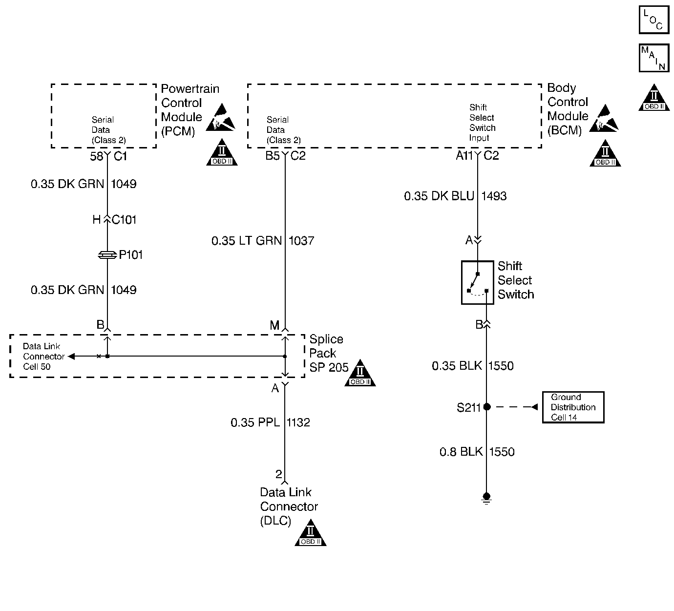
The Driver Shift Select System allows the driver to select one of two shift patterns, NORMAL or PERFORMANCE. Pressing the shift select switch button on the shifter handle changes the shift pattern.
The performance shift switch provides a ground signal to the body control module (BCM) by connecting circuits 1493 (DK BLU) and 1550 (BLK). When the BCM receives this input, it sends a message to the PCM and the instrument panel control (IPC) module. This signal activates the performance shift control program in the PCM and commands the IPC module to illuminate the PERF SHIFT indicator on the instrument panel.
The PERFORMANCE shift pattern has the following characteristics:
| • | Upshifts occur at a higher vehicle speed. |
| • | Downshifts occur at a lower percentage throttle position. |
| • | Engine torque output is increased in 2nd and 3rd gear. |
Diagnostic Aids
| • | Inspect the wiring at the PCM, the BCM, the transmission 20-way connector and all other circuit connecting points for the following conditions: |
| - | A backed out terminal |
| - | A damaged terminal |
| - | Reduced terminal tension |
| - | A chafed wire |
| - | A broken wire inside the insulation |
| - | Moisture intrusion |
| - | Corrosion |
| • | Inspect the Driver Shift Select Switch connector and the associated wiring. |
| • | Verify that any aftermarket electronic equipment is properly installed. Improperly installed aftermarket electronic equipment may modify the integrity of other systems. |
| • | Refer to General Electrical Diagnosis in Wiring Systems. |
Test Description
The numbers below refer to the step numbers on the diagnostic table.
-
This step isolates the fault to the PCM or the BCM side of the circuit by causing the BCM to illuminate the PERF SHIFT indicator if it can.
-
This step verifies the repair by comparing the characteristics of the shift at a specific throttle angle in each shift mode.
Step | Action | Value(s) | Yes | No | ||||||||||||
|---|---|---|---|---|---|---|---|---|---|---|---|---|---|---|---|---|
1 | Was the Powertrain On-Board Diagnostic (OBD) System Check performed. | -- | Go to Powertrain On Board Diagnostic (OBD) System Check in Engine Controls | |||||||||||||
Is the PERF SHIFT indicator illuminated? | -- | Go to Performance Shift Switch Malfunction in the Electrical Diagnosis Section | ||||||||||||||
3 | Replace the PCM. Refer to Powertrain Control Module Replacement/Programming in Engine Controls. Is the replacement complete? | -- | -- | |||||||||||||
In order to verify the repair, use the Scan Tool while operating the vehicle under the following conditions:
Are the shifts delayed and more firm in PERFORMANCE than when the shift select switch is in NORMAL? | -- | System OK |
