Circuit Description
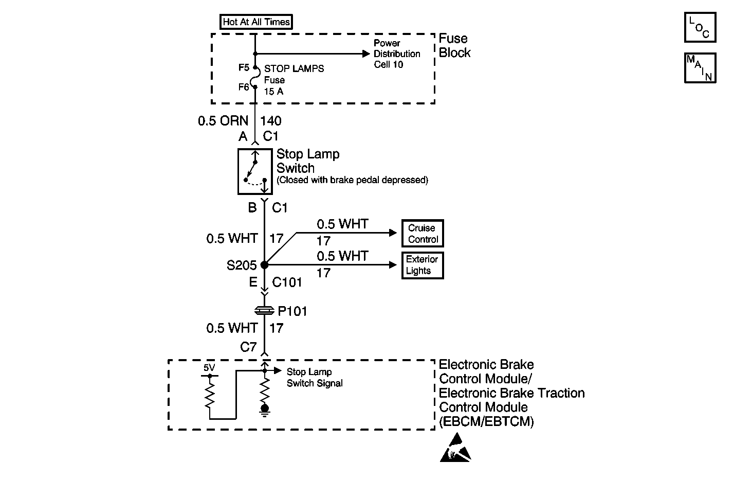
The Stoplamp Switch is a normally open switch. When the brake pedal is depressed the EBCM/EBTCM senses battery voltage. This allows the EBCM/EBTCM to determine the state of the brake lamps. A brake switch circuit open will result in a modified ABS entrance criteria and possibly false settings of excessive wheel speed variation codes (C1225 thru C1228).
Conditions for Setting the DTC
| • | The EBCM/EBTCM senses an open circuit condition for 2 seconds or more in the brake switch input circuit. |
| • | The EBCM/EBTCM senses an open circuit condition for 2 seconds or more in all brake lamps. |
| • | The EBCM/EBTCM senses an open circuit condition for 2 seconds or more in all brake lamp grounds. |
Action Taken When the DTC Sets
| • | A malfunction DTC is stored |
| • | TCS is disabled. |
| • | Traction Control indicator is turned on. |
| • | ABS remains functional. |
Conditions for Clearing the DTC
| • | Condition for DTC is no longer present and scan tool clear DTC function is used. |
| • | 100 ignition cycles have passed with no DTCs detected. |
Diagnostic Aids
| • | Possible causes: |
| - | Stoplamp switch input circuit open. |
| - | All brake lamps open. |
| - | Open brake lamp ground. |
| - | Circuit has a wiring problem, terminal corrosion, or poor connections. |
| • | It is very important that a thorough inspection of the wiring and connectors be performed. Failure to carefully and fully inspect wiring and connectors may result in misdiagnosis, causing part replacement with reappearance of the malfunction. |
| • | If an intermittent malfunction exists refer to Intermittents and Poor Connections Diagnosis in Wiring Systems. |
Step | Action | Value(s) | Yes | No | ||||||
|---|---|---|---|---|---|---|---|---|---|---|
1 | Was the Diagnostic System Check performed? | -- | ||||||||
2 | Press the brake pedal. Do all of the brake lights illuminate? | -- | Go to Exterior Lights System Check in Lighting Systems | |||||||
3 | Inspect both the EBCM/EBTCM and harness connector for the following conditions:
Are there signs of terminal damage, poor terminal contact, or terminal corrosion? | -- | ||||||||
4 | Replace all of the terminals or the connector that exhibits signs of damaged terminals, poor terminal contact, or terminal corrosion. Is the repair complete? | -- | -- | |||||||
5 |
Is the resistance within the range specified in the value(s) column? | 0-2 ohms | ||||||||
6 | Repair open or high resistance in CKT 17 between the stoplamp switch connector C1 and the EBCM/EBTCM. Refer to Wiring Repairs in Wiring Systems. Is the repair complete? | -- | -- | |||||||
7 | Replace the EBCM/EBTCM. Refer to Electronic Brake Control Module/Electronic Brake and Track Control Module Replacement . Is the replacement complete? | -- | -- |
