For 1990-2009 cars only
Removal Procedure
- Disconnect the battery ground (negative) cable. Refer to Battery Negative Cable Disconnect/Connect Procedure in Engine Electrical.
- Remove the upper intake manifold. Refer to Intake Manifold Replacement (Upper).
- Remove the left valve rocker arm cover. Refer to Valve Rocker Arm Cover Replacement (Left Front).
- Remove the right valve rocker arm cover. Refer to Valve Rocker Arm Cover Replacement (Right Rear).
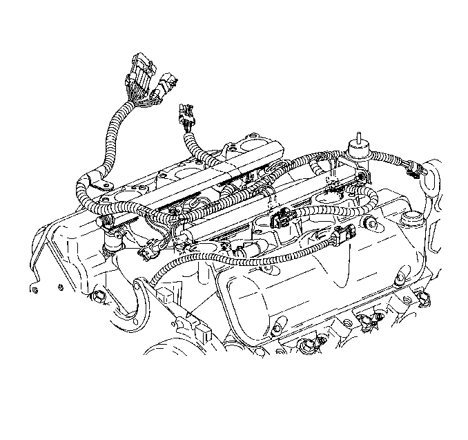
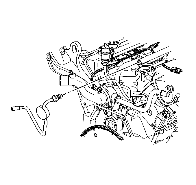
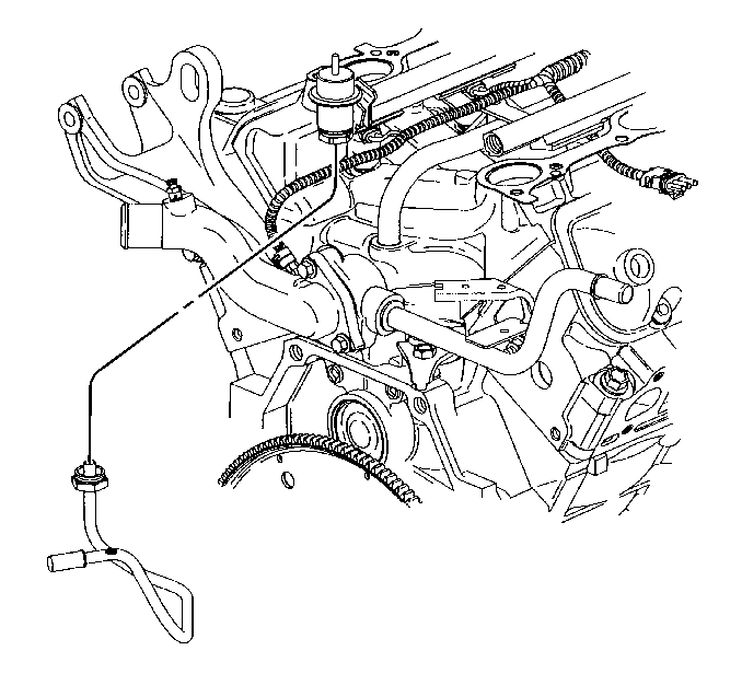
- Disconnect the engine coolant temperature (ECT) wiring harness.
- Disconnect and remove the fuel injector and manifold air pressure (MAP) wiring harness.
- Remove the fuel pipe clip bolt.
- Remove the fuel pipe clip.
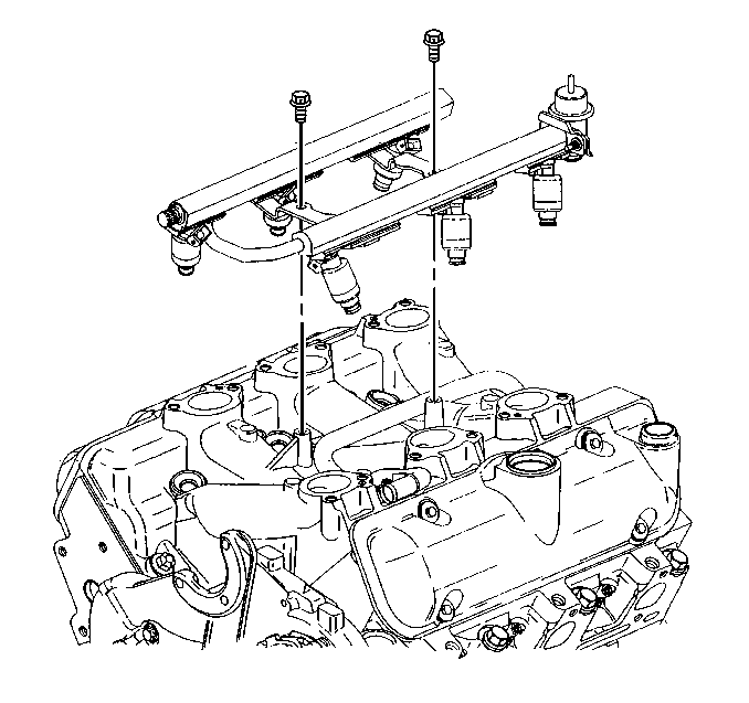
- Disconnect the fuel feed pipe from the fuel injector rail. Refer to Fuel Rail Assembly Replacement in Engine Controls-2.5 L (LB8) and 3.0 L (LW9).
- Disconnect the fuel return pipe from the fuel injector rail. Refer to Fuel Rail Assembly Replacement in Engine Controls-2.5 L (LB8) and 3.0 L (LW9).
- Remove the fuel injector rail. Refer to Fuel Rail Assembly Replacement in Engine Controls-2.5 L (LB8) and 3.0 L (LW9).
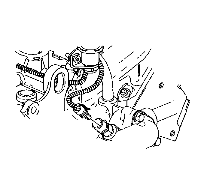
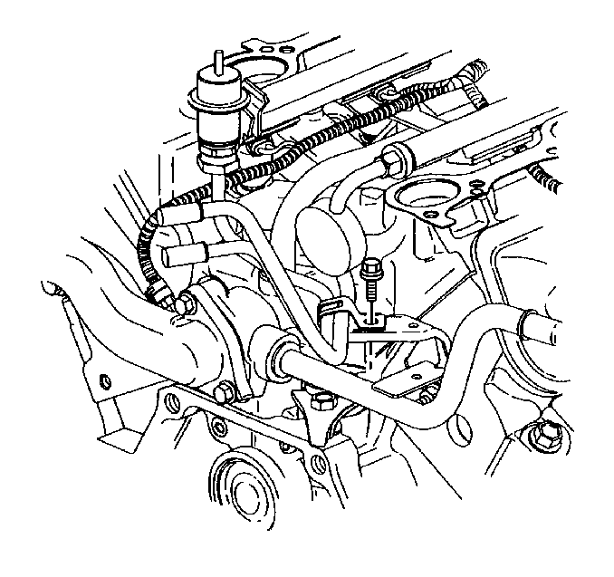
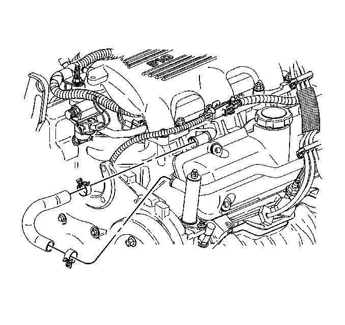
- Disconnect the power steering pump from the front engine cover and reposition aside.
- Disconnect the heater inlet pipe with heater hose from the lower intake manifold and reposition.
- Disconnect the radiator inlet hose from the engine. Refer to Radiator Hose Replacement - Inlet in Engine Cooling.
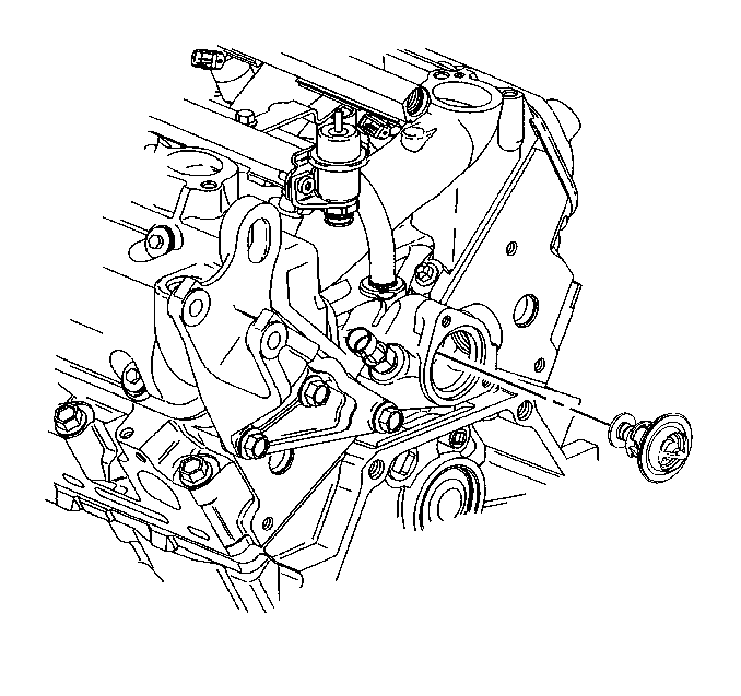
- Disconnect the thermostat bypass hose from the thermostat bypass pipe and lower intake manifold pipe.
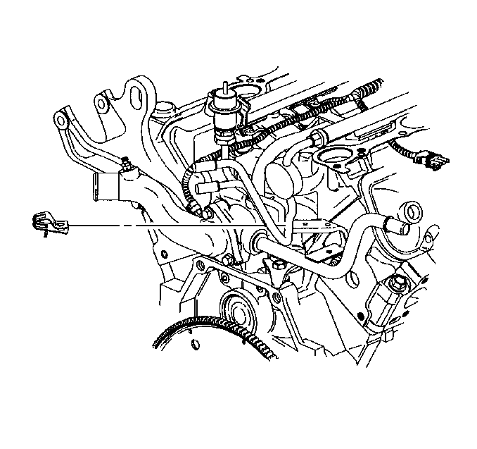
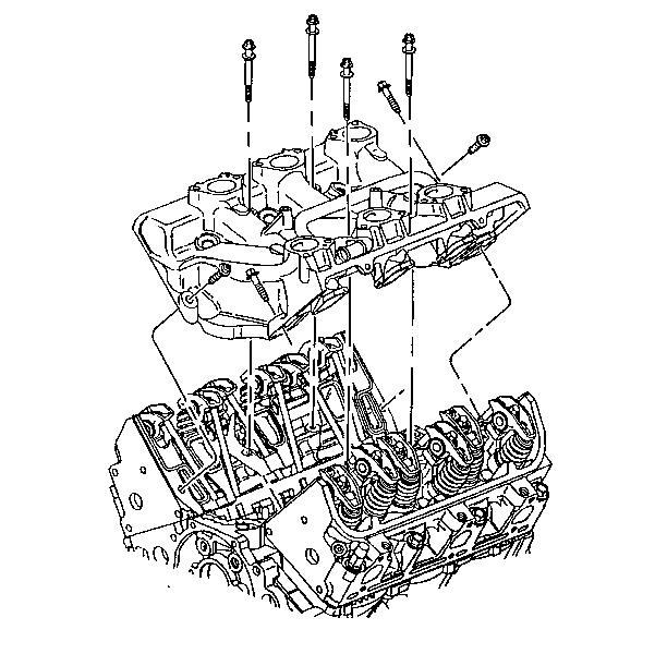
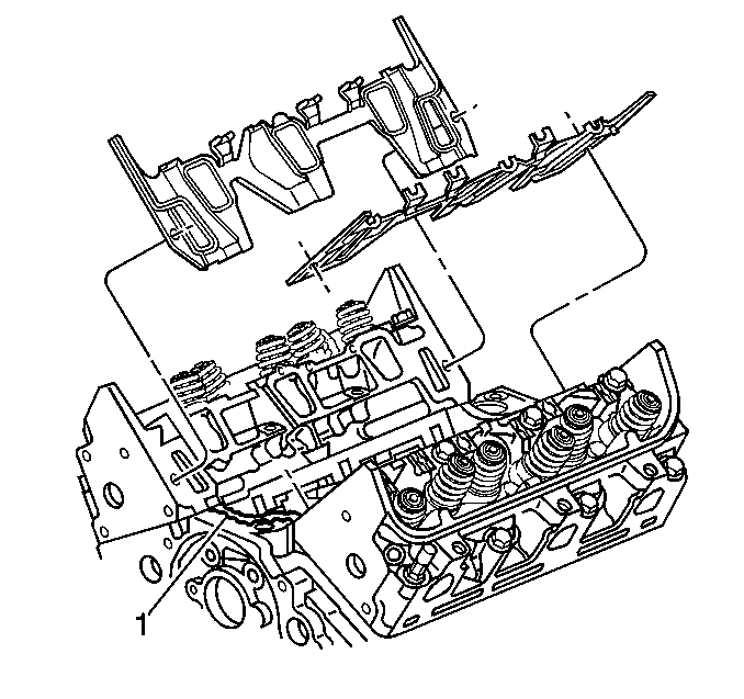
- Remove the lower intake manifold bolts.
- Remove the lower intake manifold.
- Remove the valve rocker arms and pushrods. Refer to Valve Rocker Arm and Push Rod Removal.
- Remove the lower intake manifold gaskets and seals.
- Clean the lower intake manifold gasket and seal surfaces on the cylinder heads and the engine block.
- Clean the gasket and seal surfaces on the lower intake manifold with degreaser.
- Remove all the loose RTV sealer.
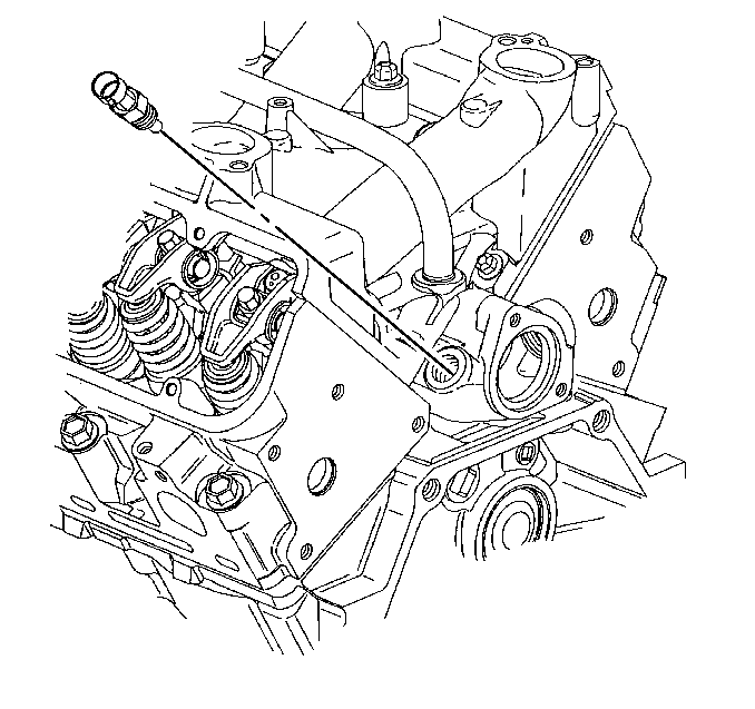
- If replacing the lower intake manifold remove the engine coolant temperature (ECT) sensor.
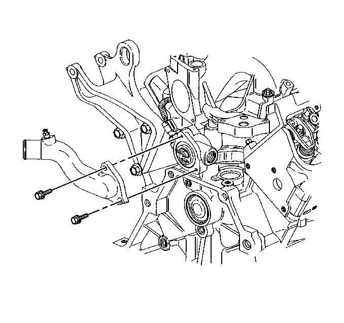
- If replacing the lower intake manifold remove the water outlet bolts.
- Remove the water outlet.
- If replacing the lower intake manifold remove the thermostat.
Important: This engine uses a sequential multiport fuel injection system. Injector wiring harness connectors must be connected to their appropriate fuel injector or exhaust emissions and engine performance may be seriously affected.
Installation Procedure
- If removed install the thermostat.
- If removed install the water outlet.
- If removed install the engine coolant temperature (ECT) sensor.
- Install the lower intake manifold gaskets.
- Install the valve rocker arms and pushrods. Refer to Valve Rocker Arm and Push Rod Installation.
- Install the lower intake manifold. Refer to Intake Manifold Installation (Lower) .
- Connect the thermostat bypass hose to the thermostat bypass pipe and lower intake manifold pipe.
- Connect the radiator inlet hose to the engine. Refer to Radiator Hose Replacement - Inlet in Engine Cooling.
- Connect the heater inlet pipe and heater hose to the lower intake manifold.
- Install the power steering pump to the front engine cover. Refer to Power Steering Pump Replacement in Power Steering System.
- Install the fuel injector rail. Refer to Fuel Rail Assembly Replacement in Engine Controls-2.5 L (LB8) and 3.0 L (LW9).
- Connect the fuel return pipe to the fuel injector rail. Refer to Fuel Rail Assembly Replacement in Engine Controls-2.5 L (LB8) and 3.0 L (LW9).
- Connect the fuel feed pipe to the fuel injector rail. Refer to Fuel Rail Assembly Replacement in Engine Controls-2.5 L (LB8) and 3.0 L (LW9).
- Install the fuel pipe clip.
- Install the fuel pipe clip bolt.
- Connect the fuel injector and manifold air pressure (MAP) wiring harness.
- Connect the engine coolant temperature (ECT) wiring harness.
- Install the right valve rocker arm cover. Refer to Valve Rocker Arm Cover Replacement (Right Rear).
- Install the left valve rocker arm cover. Refer to Valve Rocker Arm Cover Replacement (Left Front).
- Install the upper intake manifold. Refer to Intake Manifold Replacement (Upper).
- Connect the battery ground (negative) cable. Refer to Battery Negative Cable Disconnect/Connect Procedure in Engine Electrical.
Install the water outlet bolts. Refer to Water Outlet Installation.
Tighten
Tighten the engine coolant temperature (ECT) sensor to 23 N·m
(17 lb ft).
Tighten
Tighten the fuel pipe clip bolt to 8 N·m (71 lb in).
