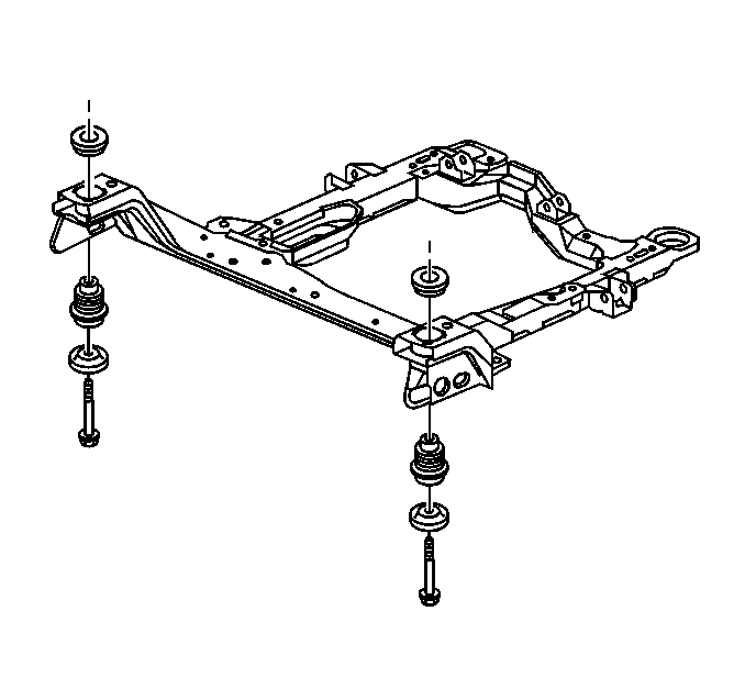
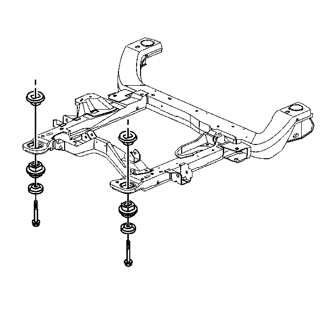
Removal Procedure
- Remove the air cleaner and the duct in order to gain access, as
needed. Refer to
Air Cleaner Assembly Replacement
(3100) or
Air Cleaner Element Replacement
(3800) in Engine Controls.
Caution: Unless directed otherwise, the ignition and start switch must be in the OFF or LOCK position, and all electrical loads must be OFF before servicing
any electrical component. Disconnect the negative battery cable to prevent an electrical spark should a tool or equipment come in contact with an exposed electrical terminal. Failure to follow these precautions may result in personal injury and/or damage to
the vehicle or its components.
- Disconnect
the negative battery cable.
- Install the Engine Support Fixture Refer to
Engine Support Fixture
(3100) or
Engine Support Fixture
(3800) in Engine Mechanical.
- Tighten the wing nuts in order to remove the slack from the hooks.
- Raise and support the vehicle. Refer to
Lifting and Jacking the Vehicle
in General Information.
- Position the jackstand under the engine for support.
- Remove the front tires and wheels. Refer to
Tire and Wheel Removal and Installation
in Tires
and Wheels.
- Disconnect the intermediate shaft from the steering gear stub
shaft. Refer to
Intermediate Steering Shaft Replacement
in Steering Wheel and Column.
- Remove the power steering cooler line pipe brackets as needed
for access. Refer to
Power Steering Cooler Pipe/Hose Replacement
with
(3100) or
Power Steering Cooler Pipe/Hose Replacement
with (3800), in
Power Steering System.
- Refer to
Steering Gear Replacement
in Power Steering System in order to remove the following
components:
| • | The steering gear mounting bolts |
| • | The support steering gear |
- Remove both of the lower ball joints from the lower control arms.
Refer to
Lower Control Arm Ball Joint Replacement
in Front Suspension.
- Remove the engine mount. Refer to
Engine Mount Replacement
with (3100) or
Engine Mount Replacement
with (3800), in Engine Mechanical.
- Remove the transaxle mount. Refer to
Transmission Mount Replacement
or in Automatic Transaxle - 4T60-E or
Transmission Mount Replacement
in Automatic Transaxle -
4T65-E.

- Have an assistant hold
the frame while you remove the body mount bolts.
- Remove the frame leaving the following components attached:
| • | Both of the lower control arms |
- Work the frame downward toward the rear of the vehicle.
- If you are replacing the frame, remove the following components.
Refer to
Lower Control Arm Replacement
in Front Suspension.
| • | Both of the lower control arms |

- If you are replacing the
frame, remove the following components:
Installation Procedure

Notice: The cab must be properly supported and the weight of the cab evenly
distributed during cab mount replacement. Failure to provide proper support
could result in damage to the vehicle.
Important: Ensure that the insulators are completely seated against the frame.
- If previously removed, install the following components:
- Install the following components. Refer to
Lower Control Arm Replacement
in Front Suspension:
| • | Both of the lower control arms |

- With the aid of an assistant,
perform the following steps:
| 3.2. | Install the new body mount bolts. Do not tighten the bolts. |
- Align the frame to the body by inserting two 19 mm (0.74 in)
diameter by 203 mm (8.0 in) long pins in the alignment holes on the
right side of the frame.
Notice: Use the correct fastener in the correct location. Replacement fasteners
must be the correct part number for that application. Fasteners requiring
replacement or fasteners requiring the use of thread locking compound or sealant
are identified in the service procedure. Do not use paints, lubricants, or
corrosion inhibitors on fasteners or fastener joint surfaces unless specified.
These coatings affect fastener torque and joint clamping force and may damage
the fastener. Use the correct tightening sequence and specifications when
installing fasteners in order to avoid damage to parts and systems.
- Install the frame
bolts.
Tighten
Tighten the frame bolts to 180 N·m (133 lb ft).
- Install the engine mounts. Refer to
Engine Mount Replacement
with(3100) or
Engine Mount Replacement
with (3800), in Engine Mechanical.
- Install the transaxle mounts. Refer to
Transmission Mount Replacement
in Automatic Transaxle - 4T60-E or
Transmission Mount Replacement
in Automatic Tranaxle - 4T65-E.
- Install the lower ball joints. Refer to
Lower Control Arm Ball Joint Replacement
in Front Suspension.
- Install the steering gear mounting bolts. Refer to
Steering Gear Replacement
in Power Steering
System.
- Install the power steering cooler line pipe brackets, If previously
removed. Refer to
Power Steering Cooler Pipe/Hose Replacement
with (3100)
or
Power Steering Cooler Pipe/Hose Replacement
with (3800),
in Power Steering System.
- Install the intermediate shaft to the steering gear stub shaft.
Refer to
Intermediate Steering Shaft Replacement
in Steering Wheel and Column - Tilt.
- Install the front tires and wheels. Refer to
Tire and Wheel Removal and Installation
in Tires
and Wheels.
- Remove the jackstand.
- Lower the vehicle.
- Remove the engine support fixture. Refer to
Engine Support Fixture
(3100) or
Engine Support Fixture
(3800) in Engine Mechanical.
- Connect the negative battery cable.
- Install the following components. Refer to
Air Cleaner Assembly Replacement
(3100) or
Air Cleaner Element Replacement
(3800) in Engine Controls:
- Inspect the front wheel alignment and adjust if needed. Refer
to
Front Camber Adjustment
in Wheel Alignment.


