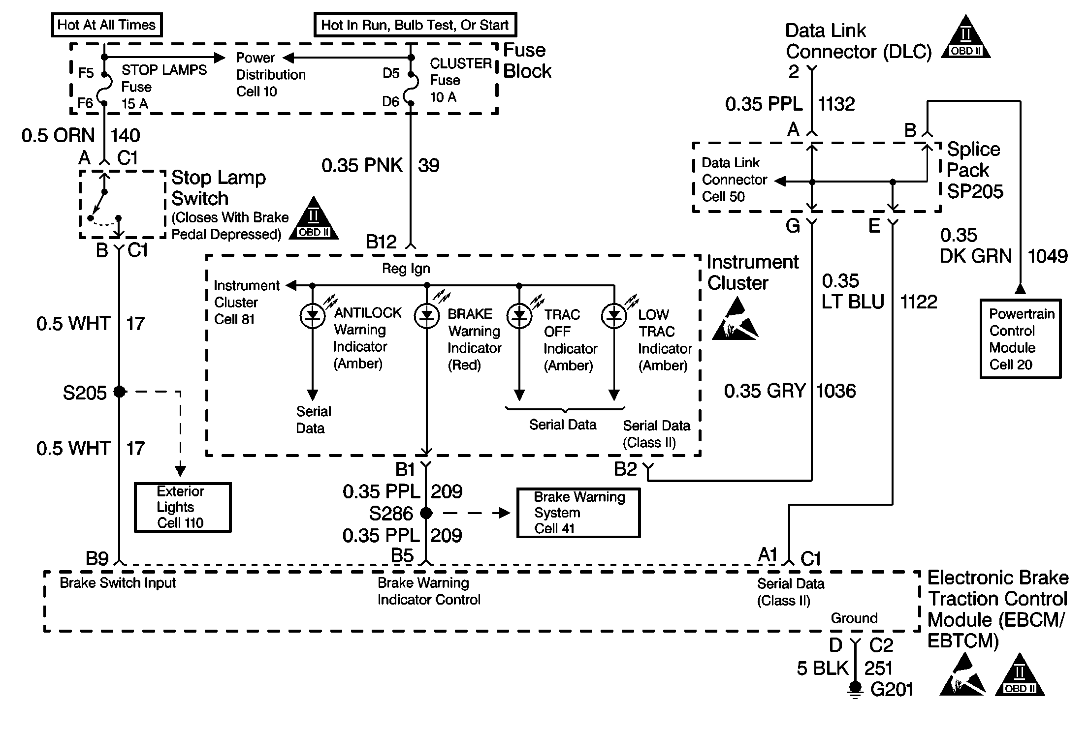
Circuit Description
This symptom table checks the following conditions:
| • | Checks the state of the ABS indicator to identify a situation in which the ABS indicator did not warn the driver of a system malfunction. |
| • | The ABS indicator is always ON. |
The EBTCM sends a message to the electronic instrument panel cluster (IPC) via the Serial Data Line and the IPC will illuminate the indicator lamp(s).
Diagnostic Aids
Use the lamp test function of the scan tool in order to command the indicator ON while looking for an malfunction in the ABS indicator.
The following conditions may cause an intermittent malfunction:
| • | A poor connection |
| • | Rubbed-through wire insulation |
| • | A broken wire inside the insulation |
Use the Lamp Test function of the Scan Tool in order to turn the indicator on while looking for an intermittent malfunction in the ABS warning indicator circuitry.
Thoroughly inspect any circuitry that may cause the intermittent complaint for the following conditions:
| • | Backed out terminals |
| • | Improper mating |
| • | Broken locks |
| • | Improperly formed or damaged terminals |
| • | Poor terminal-to-wiring connections |
| • | Physical damage to the wiring harness |
Step | Action | Value(s) | Yes | No |
|---|---|---|---|---|
1 | Was the Diagnostic System Check performed? | -- | Go to Diagnostic System Check | |
2 |
Did the amber ABS warning indicator turn on? | -- | System OK | |
3 | Repair the instrument panel cluster. Refer to Instrument Cluster, Cell 81, in Electrical Diagnosis. Is the repair complete? | -- | Go to Diagnostic System Check | -- |
