SERVICE MANUAL UPDATE SEC.8A- ELECTRICAL DIAGNOSIS

VEHICLES AFFECTED: 1989 "W" CAR
The following pages reflect product changes. These pages are contained herein:
8A-1-0 INDEX
8A-1-1 INDEX
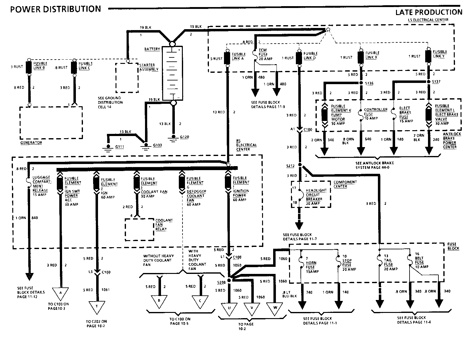
8A-10-0-A POWER DISTRIBUTION
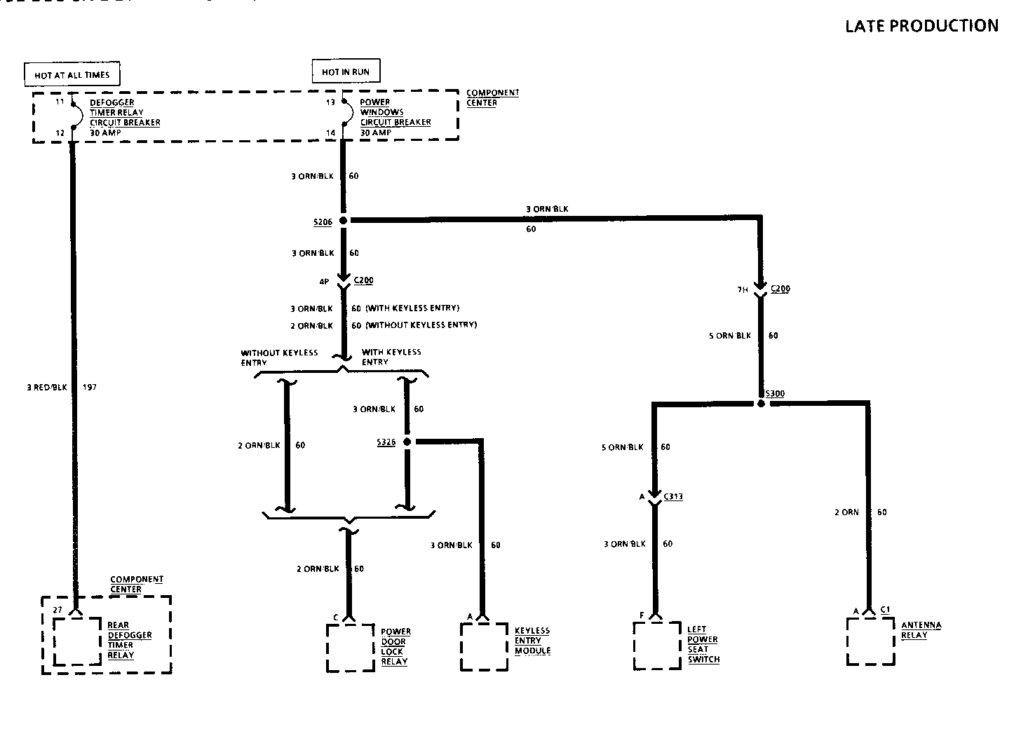
8A-11-8-A FUSE BLOCK DETAILS: COMPONENT CENTRE
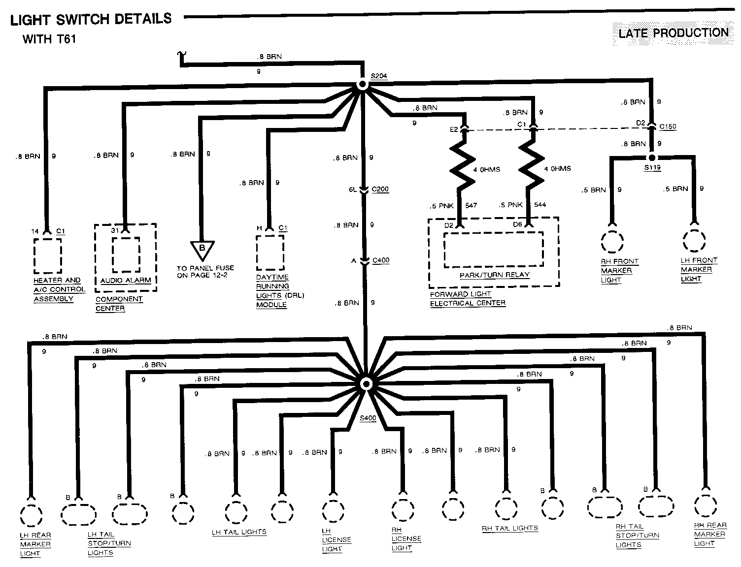
8A-12-3-A LIGHT SWITCH DETAILS
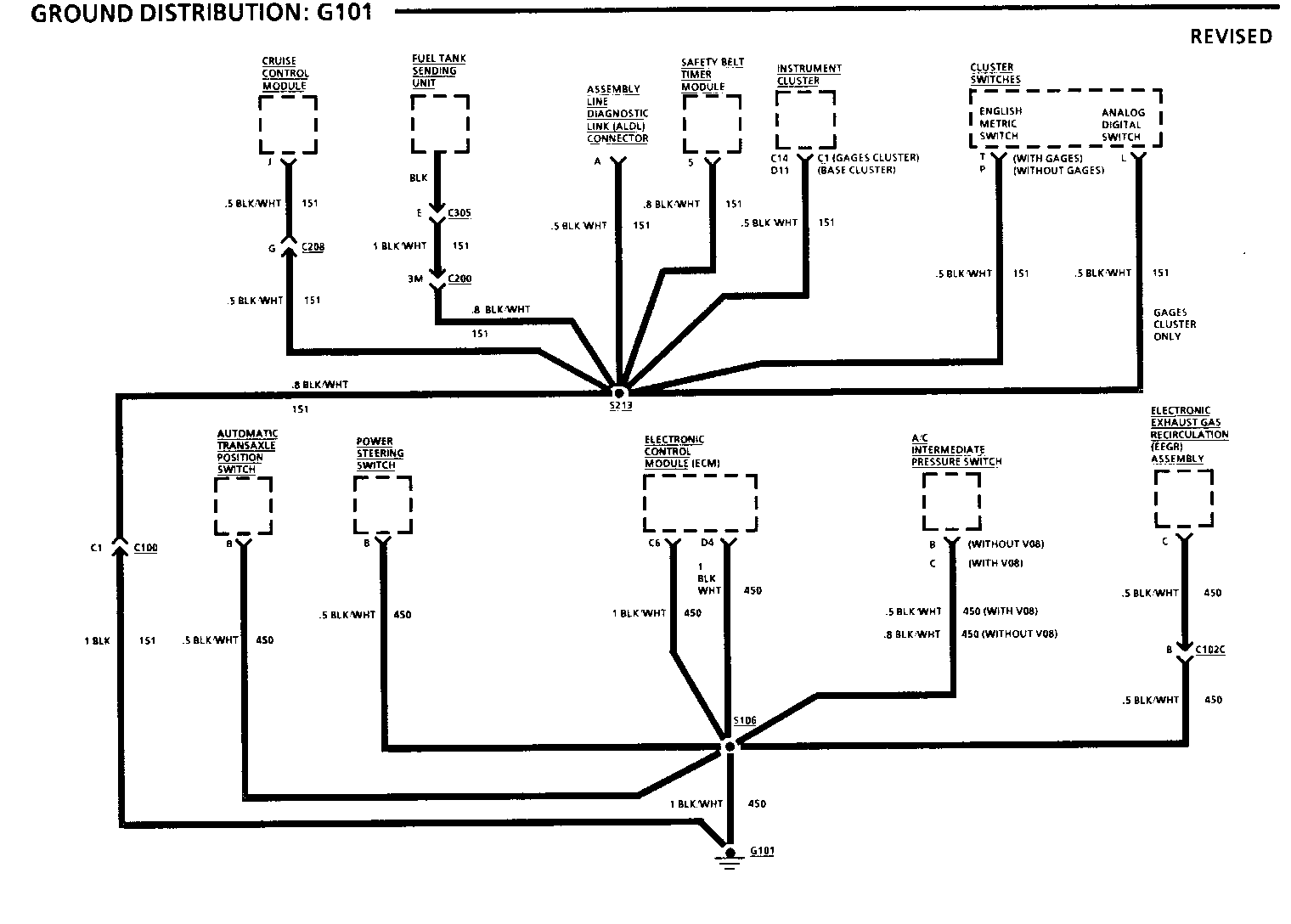
8A-14-0 GROUND DISTRIBUTION: G101
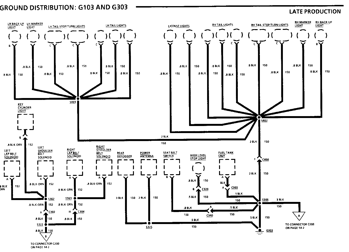
8A-14-1-A GROUND DISTRIBUTION: G103 and G303
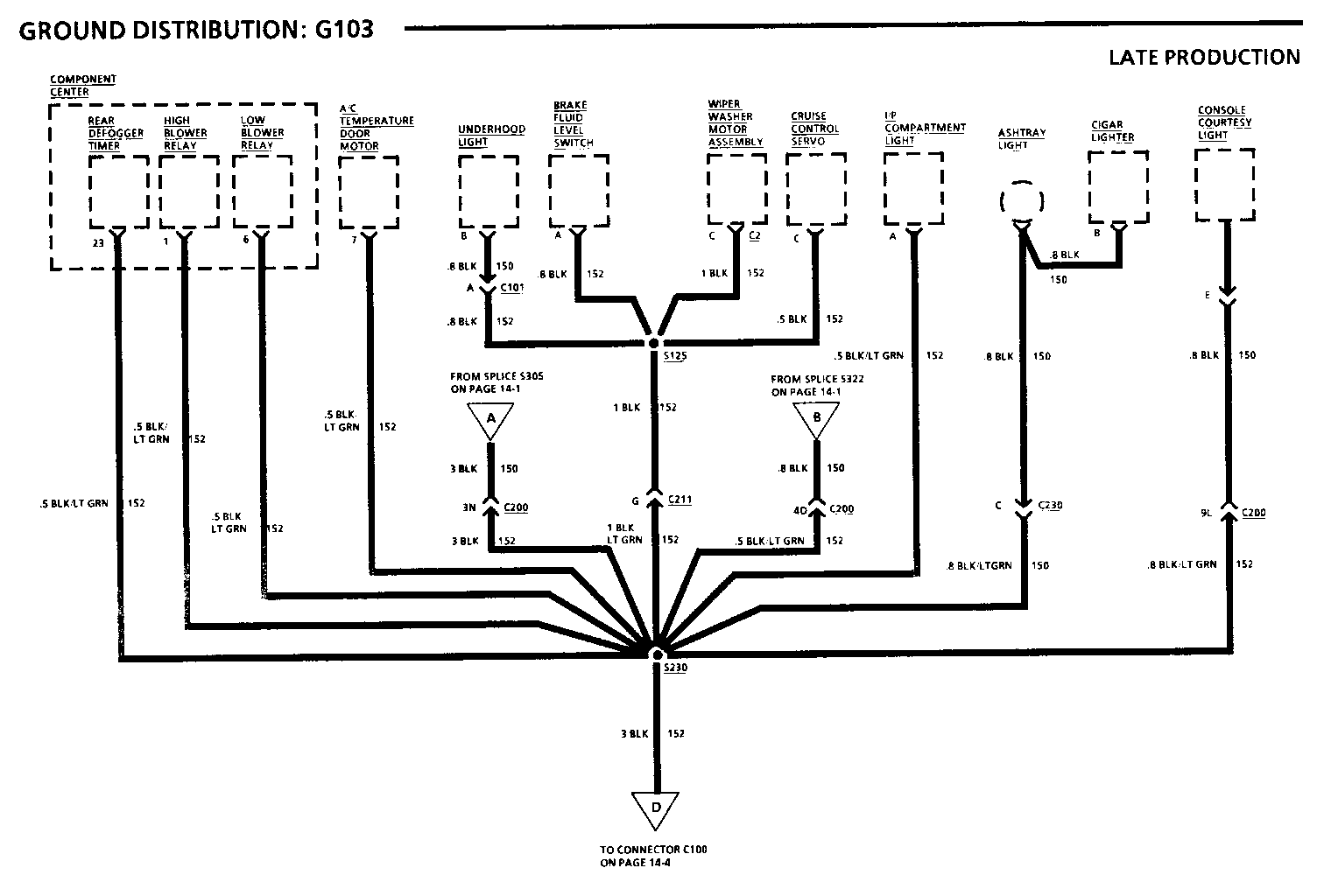
8A-14-2-A GROUND DISTRIBUTION: G103
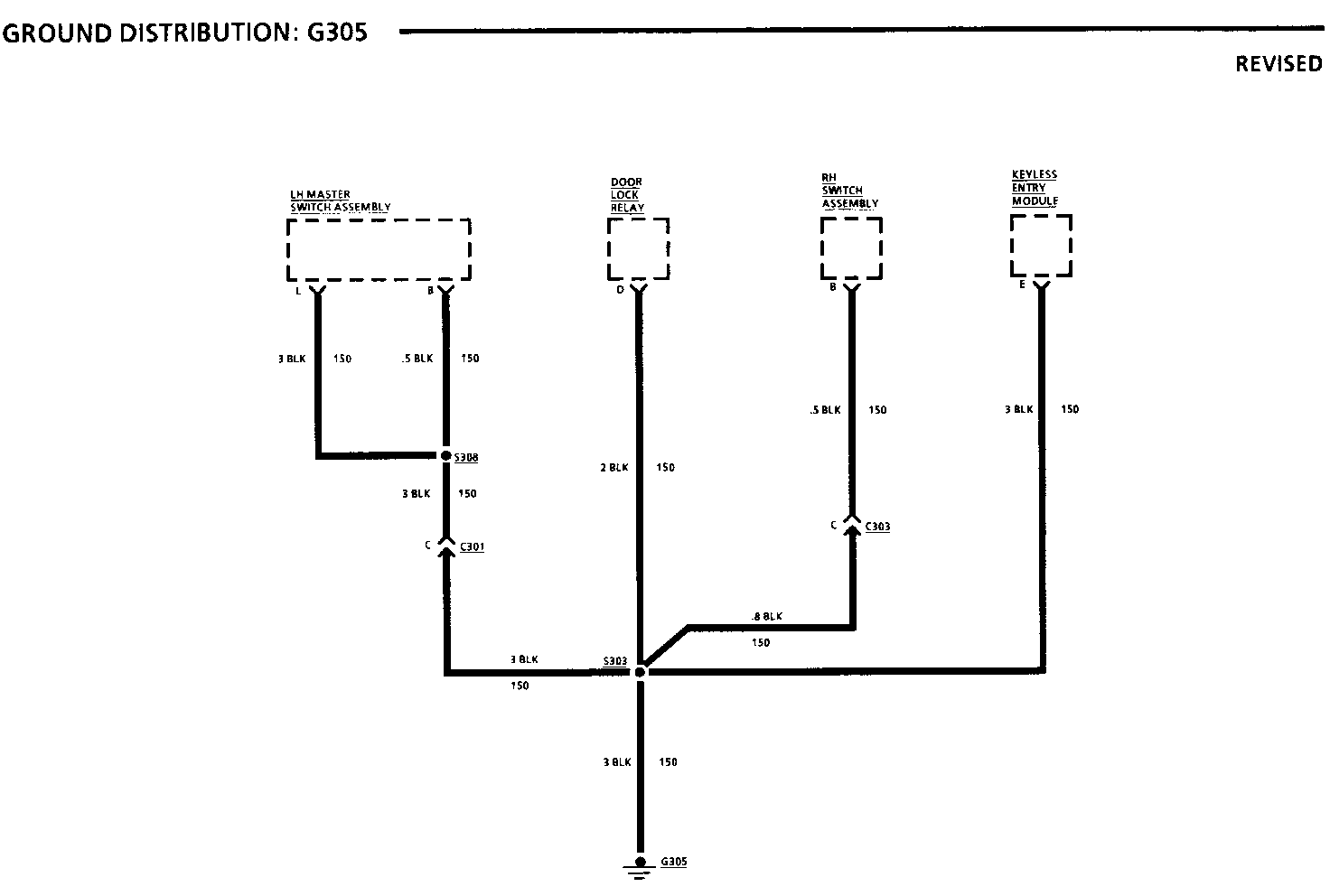
8A-14-6 GROUND DISTRIBUTION: G305
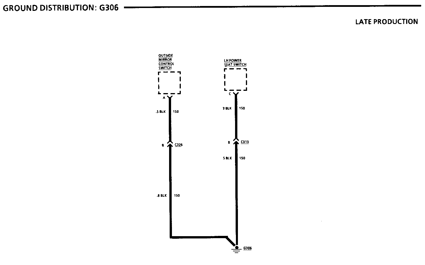
8A-14-7-A GROUND DISTRIBUTION: G306
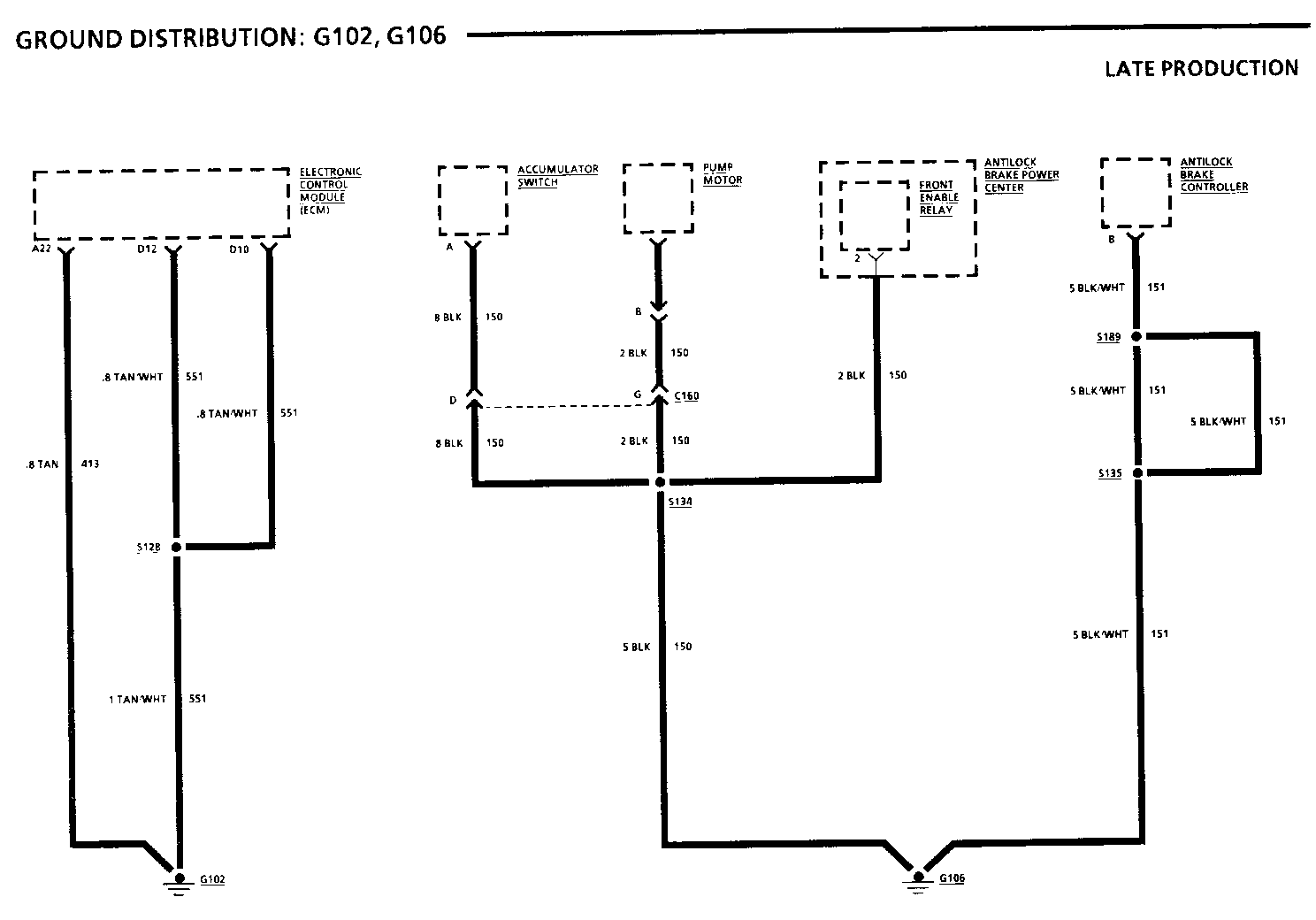
8A-14-8-A GROUND DISTRIBUTION: G102 and G106
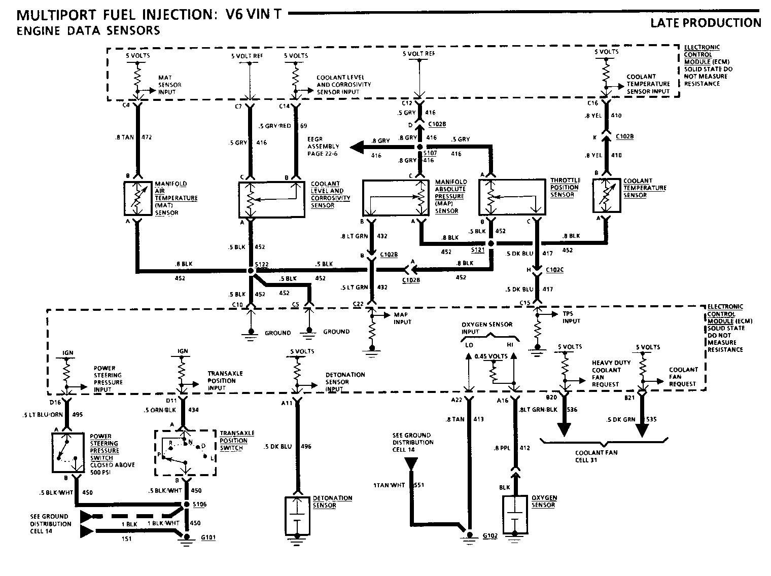
8A-22-4-A MULTI-PORT FUEL INJECTION: V6 VIN T Engine Data Sensors
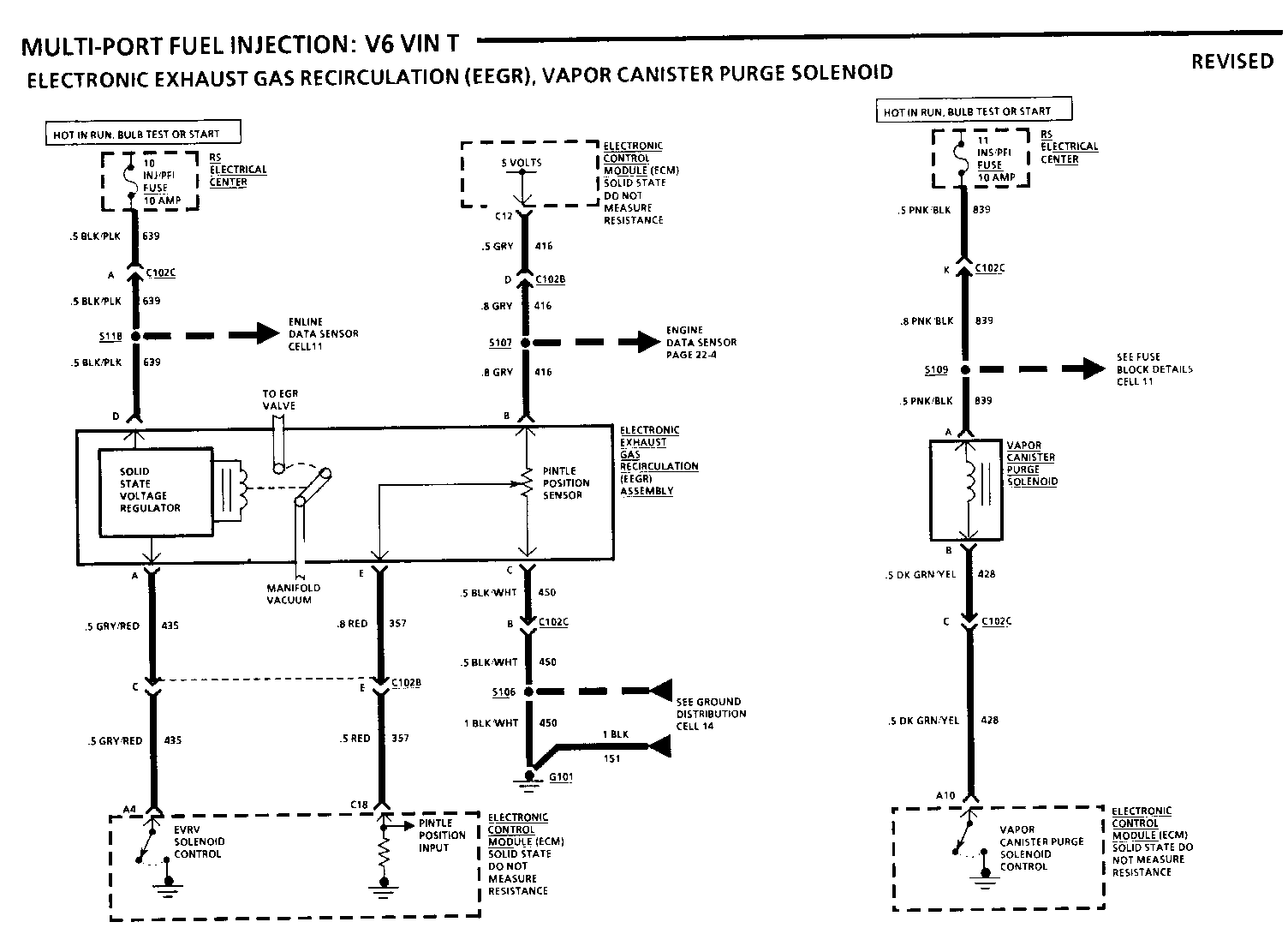
8A-22-6 MULTI-PORT FUEL INJECTION: V6 VIN T Electronic Exhaust Gas Recirculation (EEGR), vapour canister purge solenoid
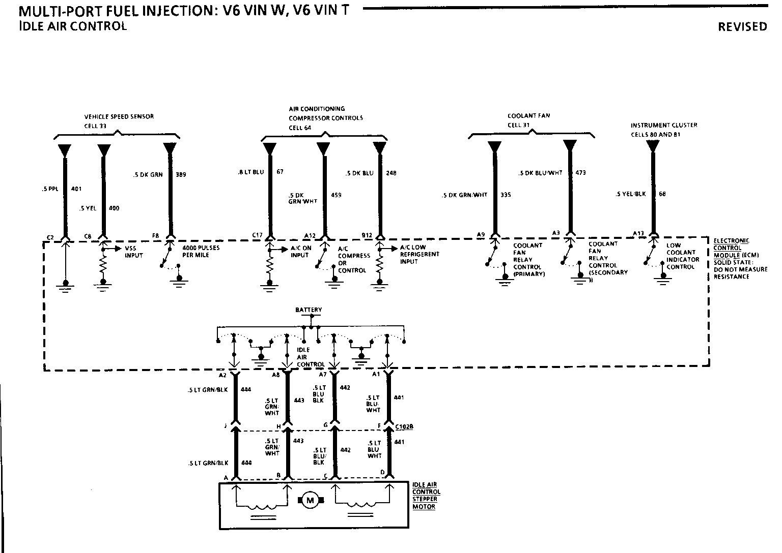
8A-22-7 MULTI-PORT FUEL INJECTION: V6 VIN W, V6 VIN T, Idle Air Control
8A-33-2 VEHICLE SPEED SENSOR
8A-33-3 VEHICLE SPEED SENSOR
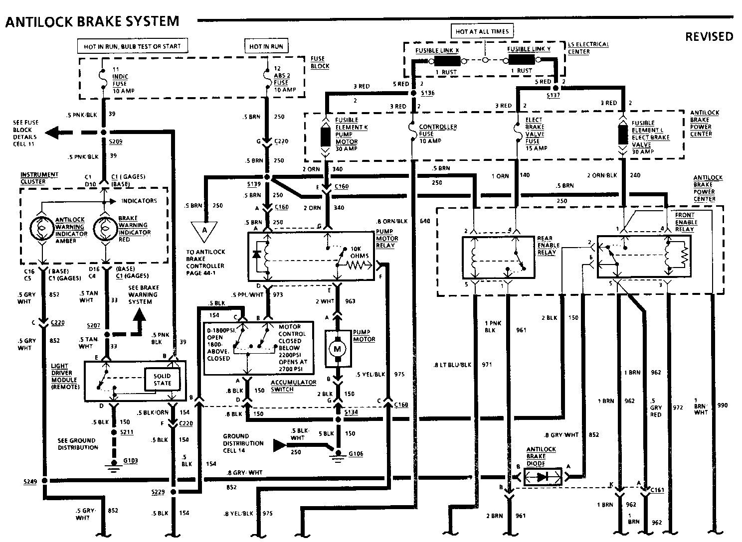
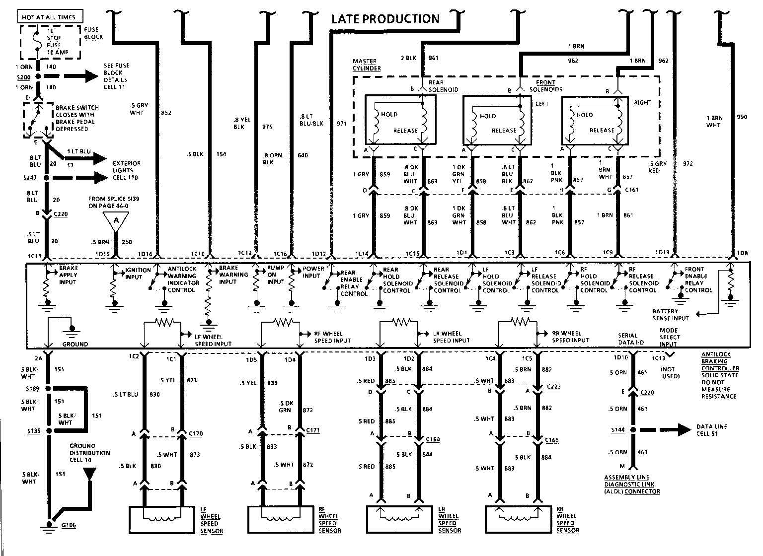
8A-44-0 ANTILOCK BRAKE SYSTEM
8A-44-1-A ANTILOCK BRAKE SYSTEM
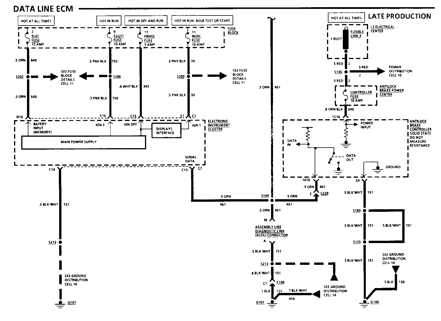
8A-51-1 DATA LINE ECM
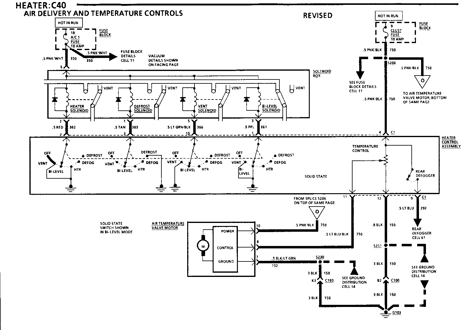
8A-60-1 HEATER: C40 Air Delivery and temperature controls
8A-64-4 AIR CONDITIONING: C67 COMPRESSOR CONTROLS
8A-64-5 AIR CONDITIONING: C67 COMPRESSOR CONTROLS
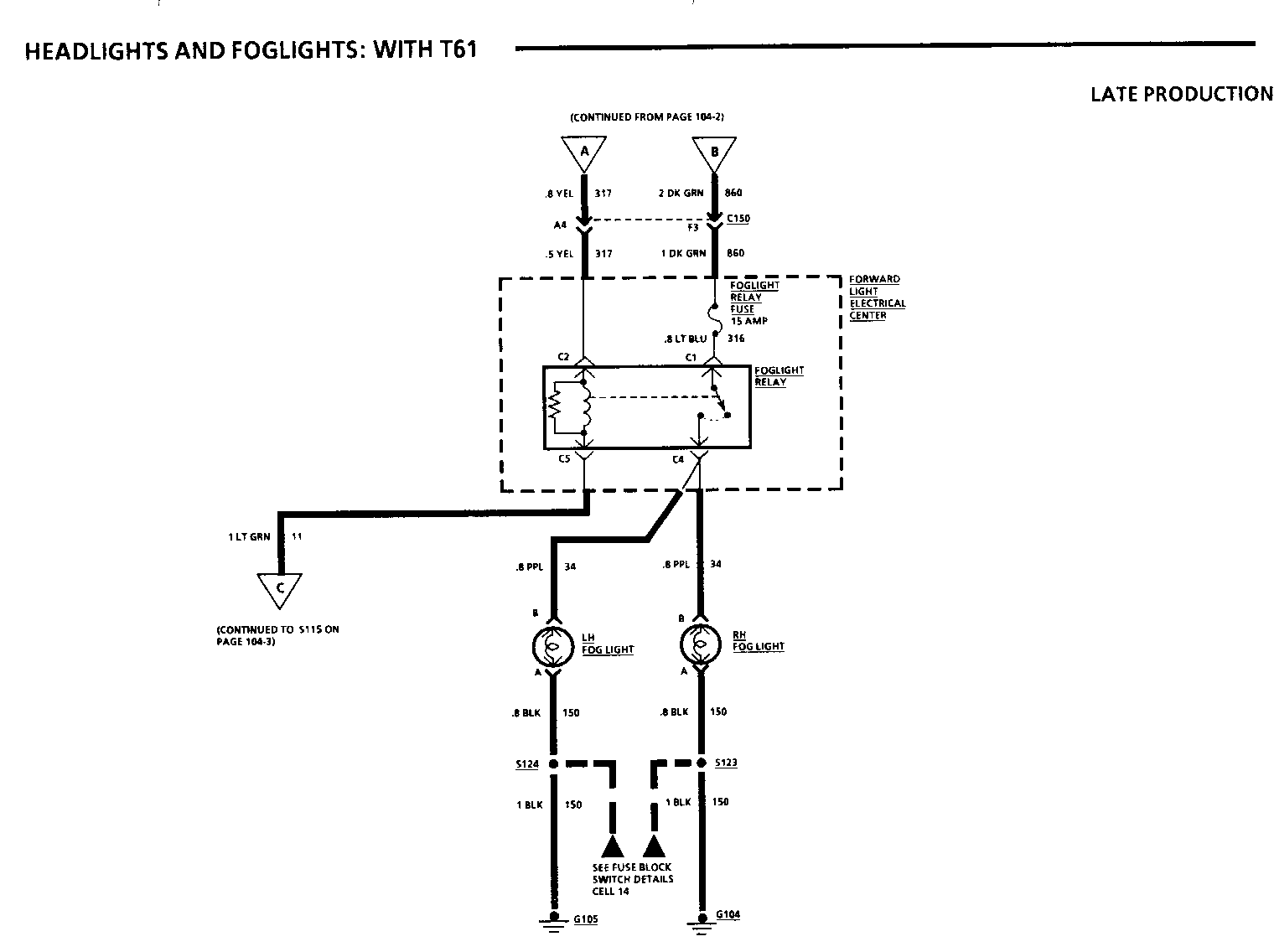
8A-104-4A HEADLIGHTS AND FOGLIGHTS: With T61
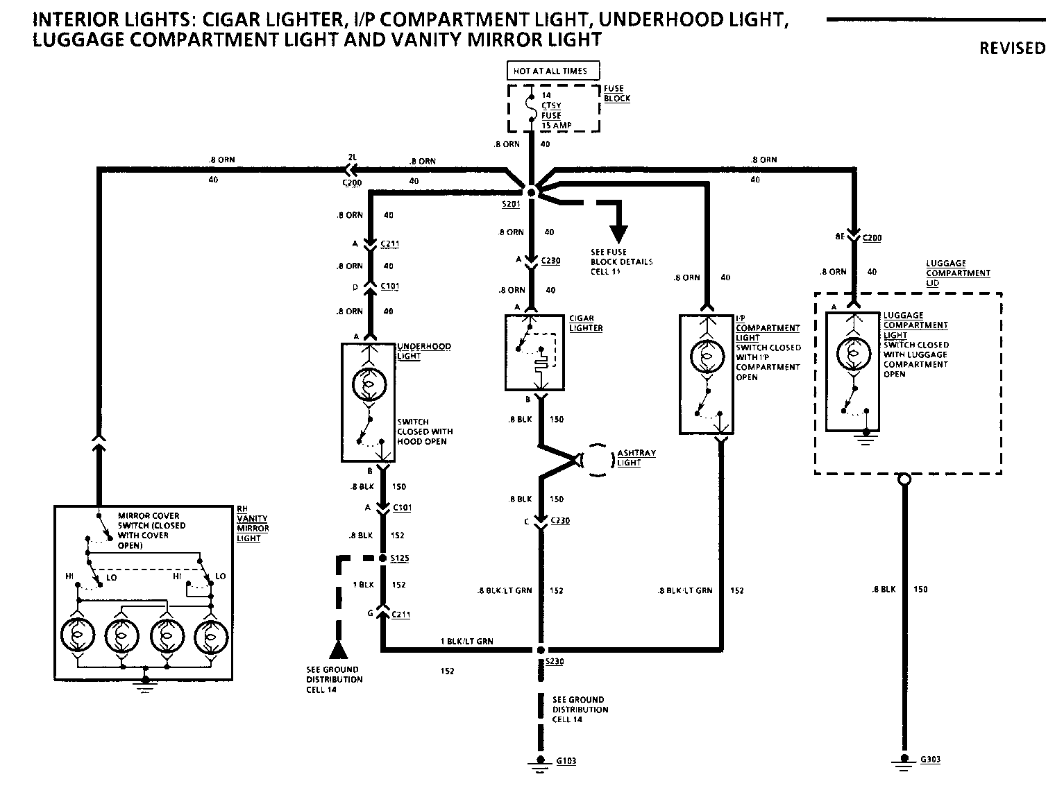
8A-114-0 INTERIOR LIGHTS: Cigar lighter, I/P compartment light, underhood, luggage compartment light and vanity mirror light
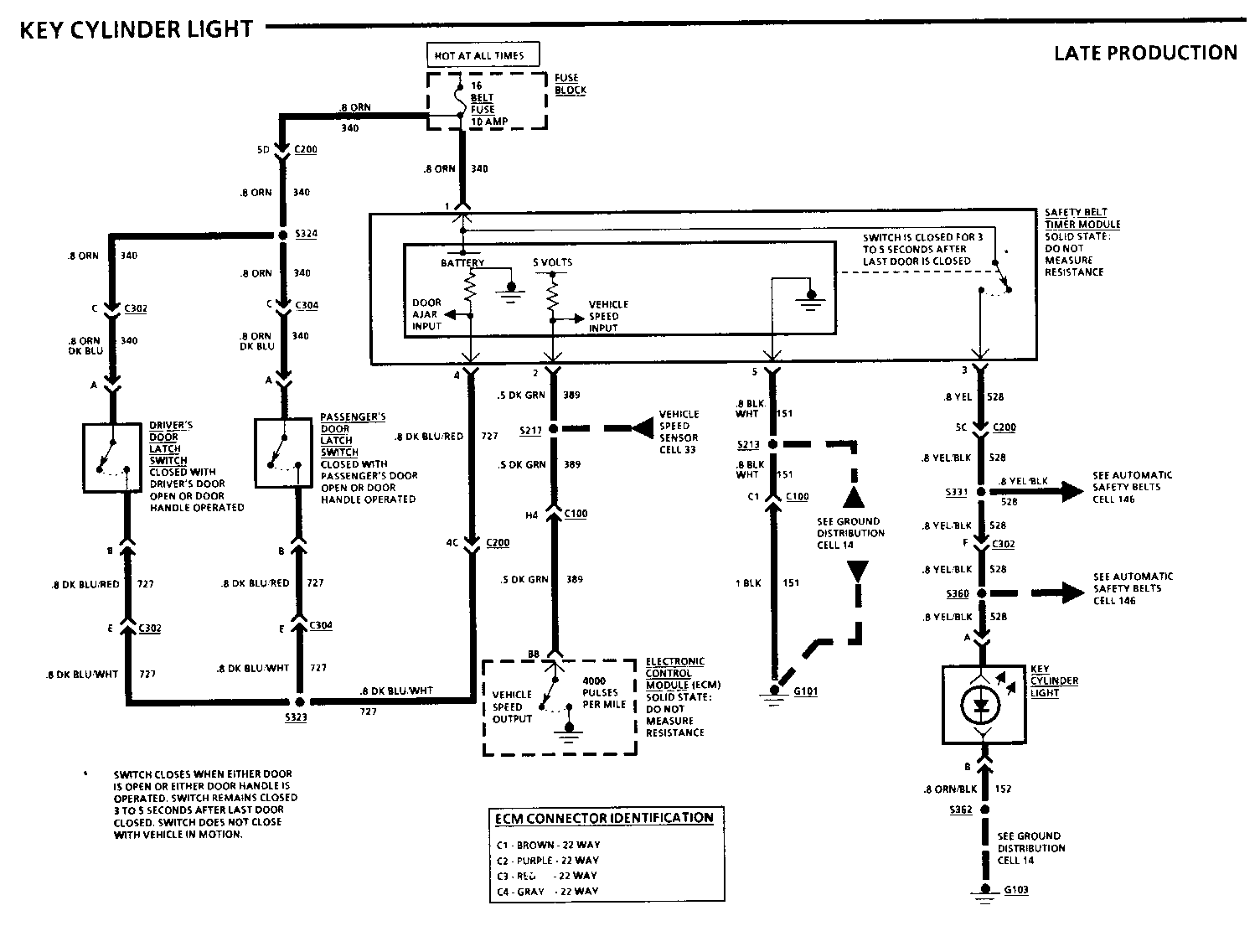
8A-115-0-A KEY CYLINDER LIGHT
8A-115-1-A KEY CYLINDER LIGHT
8A-115-2-A KEY CYLINDER LIGHT
8A-120-0 POWER WINDOWS
8A-120-2 POWER WINDOWS
8A-120-3 POWER WINDOWS
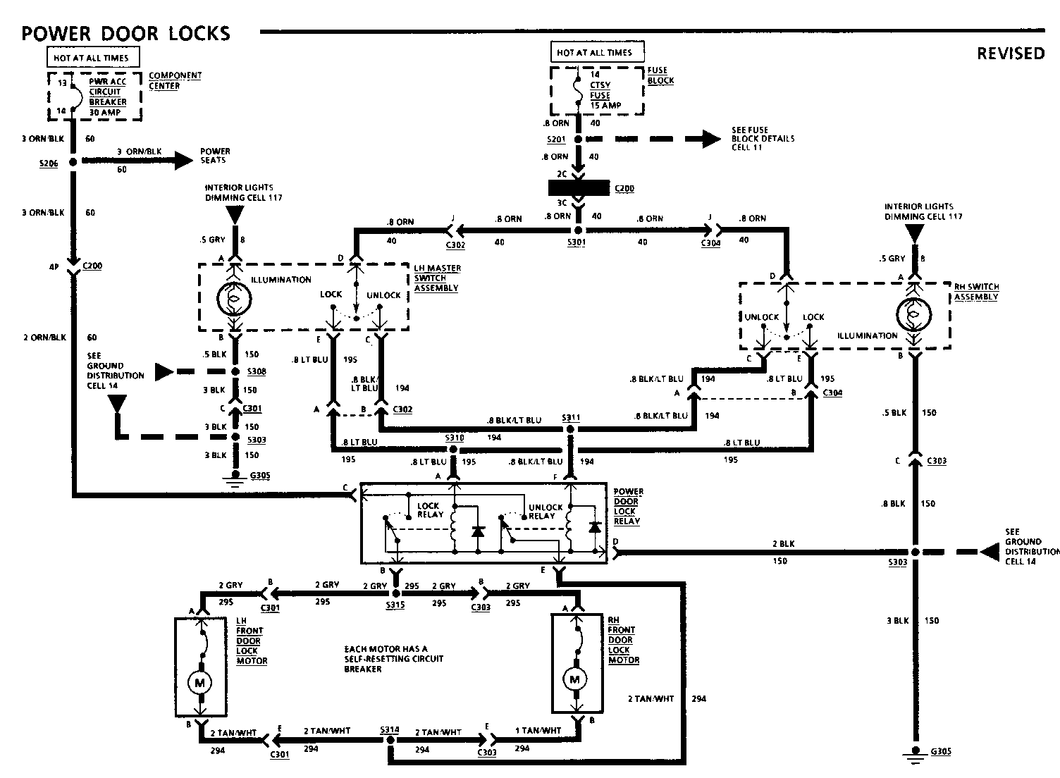
8A-130-0 POWER DOOR LOCKS
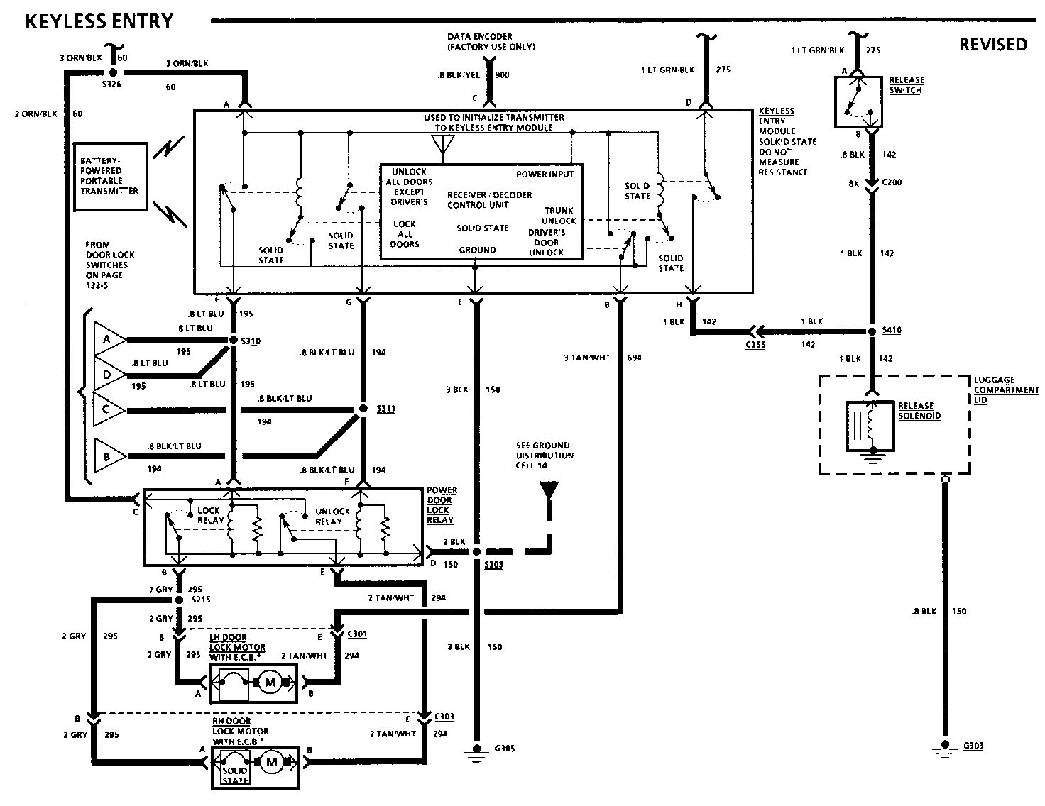
8A-132-1 KEYLESS ENTRY
8A-132-8 KEYLESS ENTRY
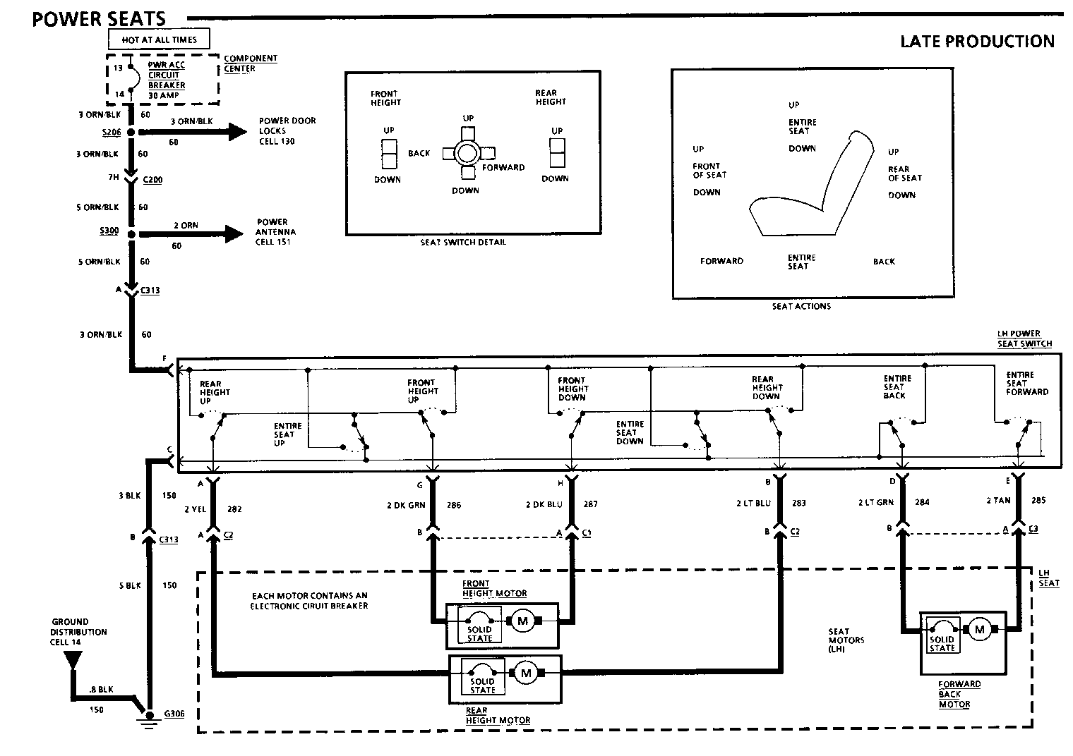
8A-140-0-A POWER SEATS
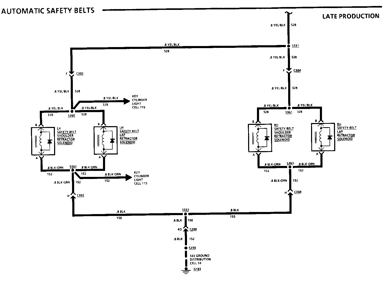
8A-146-0-A AUTOMATIC SAFETY BELTS
8A-146-1-A AUTOMATIC SAFETY BELTS
In addition, the following pages should be revised to reflect minor changes for late production, as noted:
8A-10-3 Change the RED/WHT (2) wire to 3 RED (2)
8A-11-0 Change terminal B of the Turn Flasher to terminal A. Change terminal C of connector Cl to C of C2 on the Daytime Running lights (DRL) Module.
8A-11-1 Change the .8 ORN (740) wire between Fuse 7 Horn Fuse and Connector C150 terminal F2 to .8 LT/BLU/BLK (740). Change terminals C1 and C5 of the Horn Relay to B1 and B5.
8A-11-3 Change the .5 PNK/BLK (439) wire between connector C100 terminal C2 and terminal B10 of the Electronic Control Module (ECM) to .8 PNK/BLK (439).
8A-11-4 Change all .8 ORN/DK BLU (340) wires from splice S324 to .8 ORN.
8A-11-5 Change the .5 WHT/BLK (343) wire between Fuse 17 PRNDL Fuse and terminal C15 of connector C1 to .8 WHT/BLK (343). Change terminal 4 of the Heater and A/C Control Assembly to terminal 4 of connector Cl.
8A-11-11 Change Electronic Vacuum Regulator Valve (EVRV) to Electronic Exhaust Gas Recirculation (EEGR) Assembly. Change terminal B of the Electronic Exhaust Gas Recirculation (EEGR) Assembly to terminal D.
8A-12-0 Change terminal P of the Light Switch to terminal 0. Change terminal B2 of the Foglight Relay to C2.
8A-12-1 Delete the Daylight Running Lights (DRL) Module and the .8 BRN (9) wire. Change all .8 BRN/WHT (9) wires to .8 BRN (9).
8A-12-2 Change the 2 YEL (307) wire to 2 YEL (907). Change terminal P of the Light Switch to terminal 0. Change terminal B2 of Foglight Relay to terminal C2.
8A-12-4 Change all .8 GRY (8) wires from splice S302 to .5 GRY (8).
8A-22-0 Change .5 PNK/BLK (439) wire between connector C100 terminal C2 and terminal B10 of the Electronic Control Module (ECM) to .8 PNK/BLK
Change terminal CL of the Electronic Control Module (ECM) to terminal C6.
8A-22-1 Change terminal C1 of the Direct Ignition System (D15) to A of connector C1
8A-22-3 Change the 1 TAN/WHT (120) wire between terminal A2 of C100 and terminal 4N of connector C200 to 1 GRY (120). Change See Ground Distribution Cell 11 to See Fuse Block Details Cell 11.
8A-30-0 Change the 3 RED/WHT (2) to RED (2). Change the .5 BRN/WHT (25) wire between terminal G2 of connector C102C and terminal G of connector C102 to .5 BRN (25).
8A-31-0 Change the .8 DK GRN/WHT (335) wire to .5 DK GRN/WHT (335). Change the .8 DK BLU/WHT (473) wire to .5 DK BLU/WHT (473).
8A-31-1 Change the .8 LT GRN/BLK (536) wire to .5 LT GRN/BLK (536). Change all .8 BLK (452) wires from splice S122 to .5 BLK (452).
8A-31-2 Change .5 BLK/WHT (450) wire to .8 BLK/WHT (450). Change all .8 BLK (452) wires from splice S122 to .5 BLK (452).
8A-34-0 Change .8 GRY/BLK (87) wires to .5 GRY/BLK (87).
8A-34-1 Change .5 BLK (150) wire to .5 BLK (152).
8A-40-0 Change .8 ORN (740) wire to .8 LT BLU/BLK (740). Change terminals C1, C2, C4, and C5 of the Horn Relay to Bl, B2, B4, and B5.
8A-41-0 Change .8 BLK (150) wire and 1 BLK (150) wire to .8 BLK (152) and 1 BLK (152).
8A-44-2 Add S189 - ABS Harness, below RH front seat - 201-15-B.
8A-51-3 Add S189 - ABS Harness, below RH front seat - 201-15-B.
8A-60-0 Change the .5 ORN (52) wire to 1 ORN (52).
8A-60-2 Add another .5 PNK/WHT (350) wire from Fuse 18 A/C referring to Fuse Block Details Cell 11.
8A-63-0 Change .5 ORN (52) wire to 1 ORN (52).
8A-64-0 Change .5 DK GRN/YEL (459) wire to .5 DK GRN/WHT (459).
8A-65-0 Add another .5 PNK/WHT (350) wire from Fuse 18 A/C 1 referring to Fuse Block Details Cell 11.
8A-76-0 Change .8 BLK/LT GRN (238) wire to .5 BLK/PNK (238). Change all .8 BLK (150) wire to .5 BLK (150).
8A-80-1 Change terminal P of the Light Switch to terminal 0.
8A-80-2 Change .8 PPL (30) wire to 1 PPL (30).
8A-81-0 Change .5 WHT/BLK (343) wire to .8 WHT/BLK (343).
8A-81-1 Change .8 PPL (30) wire to 1 PPL (30).
8A-81-4 Change terminals C112 and D14 of the Electronic Instrument Cluster to D1 and C14.
8A-90-0 Change 1 BLK (150) wire to 1 BLK (152).
8A-91-0 Change 1 BLK (150) wire to 1 BLK (152).
8A-100-1 Change terminals C1, C2, C4, and C5 of the Foglight Relay to B1, B2, B4, and B5.
8A-104-8 Change (YEL/BLK) wires to (YEL) and (PNK/BLK) wires to (PNK/WHT).
8A-110-0 Change terminals A and B of the Turn Flasher to B and A.
8A-110-1 Change .8 BLK/WHT (150) wires from splices S402 and S403 to .8 BLK (150).
8A-110-2 Change terminals A and B of the Turn Flasher to terminals B and A.
8A-110-3 Change .8 BLK/WHT (150) wires from splices S402 and S403 to .8 BLK (150).
8A-110-5 Change .8 BRN/WHT (9) wires to .8 BRN (9). Change .8 BLK/WHT (150) wires to .8 BLK (150).
8A-112-0 Change .8 LT GRN/WHT (24) wire to .8 LT GRN (24). Change .8 BLK/WHT (150) wires to .8 BLK (150).
8A-114-3 Add G303 - under RH Front Seat - 201-15-C.
8A-117-0 Change terminal P of the Light Switch to terminal 0.
8A-117-1 Change .8 GRY (8) wires to .5 GRY (8).
8A-120-1 Add S231 I/P harness, behind RH side of I/P - 201-9-A.
8A-130-1 Add S308 LH door harness, inside front of door -201-18-A.
8A-132-2 Change terminals C and E of the LH Master Switch Assembly to terminals E and C. Change connector C302 to C304. Change terminals C and E of the RH Switch Assembly to terminals E and C.
8A-132-5 Change PPL (900) wire to BLK/YEL (900).
8A-134-0 Change .8 LT GRN/WHT (24) wire to .8 LT GRN (24). Change all wires from splice S410 to 1 BLK (142). Change .8 BLK (142) wire to the Release Solenoid to 1 BLK (142).
8A-150-1 Change .8 BLK/LT BLU (153) wires to .8 BLK/LT BLU (153).
8A-150-2 Change .8 BLK/LT BLU (153) wires to .5 BLK/LT BLU (153). Change the following wires:
.5 BLK/WHT (152) to .5 BLK (152) .5 DK GRN/WHT (835) to .5 BK GRN (152) .5 PPL/YEL (724) to .5 PPL/WHT (724)
Change the .8 DK GRN (835) wire to .5 DK GRN (835). Change the .5 BRN (726) wire to .5 YEL (726).
8A-150-4 Change the following wires:
.5 ORN/BLK (640) to .5 ORN (640) .5 YEL/BLK (43) to .5 YEL (43) .5 DK GRN/ORN (606) to .5 DK GRN/WHT (606) .5 WHT/DK GRN (607) to .5 WHT/BLK (607).
Change .8 BLK/LT BLU (153) wires to .5 BLK/LT BLU (153).
8A-150-6 Change .8 BLK/LT BLU (153) wires to .5 BLK/LT BLU (153).
8A-151-0 Change the .8 PNK (143) wire from terminal 18 of C1 of the Radio Receiver to terminal 18 of C207 to .5 PNK/BLK (143). Delete one of the 5 ORN/BLK (60) wires from splice S300 to the power seats. Change the 2 ORN/BLK (60) wire to 2 ORN (60).
8A-201-15 Add splice S189 next to splice S229.
Chassis Service Page/REvision Manual Page and Category Air Conditioning ----------- ------------ Air Delivery and Temperature Controls...... 65-0 .............. 65-0 3 Blower Controls ............................63-0 .............. 63-0 3 Compressor Controls ........................64-0...... 64-0 3, 64-4 2, 64-5 2 System Check............................. 62-0 Antilock Brake System ....................... 44-0..44-0 2,44-1-A 1,44-2 3 Audio Alarm System........................... 76-0................76-0 3 Automatic Safety Belts...................... 146-0... 146-0-A 1, 146-1-A 1 Brake Warning System......................... 41-0................41-0 3 Charging System.............................. 30-3................30-0 3 Cigar Lighter............................... 114-2 ..............114-0 2 Component Center Automatic Seatbelts Fuse....................11-4................11-4 3 Foglight Relay Fuse....................... 11-7 Headlight Circuit Breaker...................11-7 Power Windows Circuit Breaker ..............11-7 Component Location Views.....................201-0.............. 201-15 3 Connectors...................................202-0 Coolant Fans Base.........................................31-2.................31-2 3 Heavy Duty V08...............................31-0.........31-0 3, 31-1 3 31-2 3 Cruise Control.................................34-0.........34-0 3, 34-1 3 Data Line......................................51-0.......51-1-A 1, 51-3 3 Defogger (Rear) ...............................61-0 Electronic Instrument Cluster: Base ...........80-0.........80-1 3, 80-2 3 Electronic Instrument Cluster: UB3.............81-0.........81-0 3, 81-1 3, 81-4 3 Engines Multi-Port Fuel Injection V6 VIN W, V6 VIN T ....................................22-0........22-0 3, 22-1 3, 22-3 3, 22-4-A 1, 22-6 2, 22-7 2 Fuse Block Details............................ 11-0........11-0 3, 11-1 3 11-3 3, 11-4 3, 11-5 3 11-8 1, 11-11 3 Gages Base Cluster Fuel.......................................80-2................80-2 3 Gages (UB3) Cluster Coolant Temperature....................... 81-0 ...............81-0 3 Fuel...................................... 81-0................81-0 3 Odometer.................................. 81-0................81-0 3 Oil Pressure ............................. 81-0................81-0 3 Speedometer................................81-0................81-0 3 Tachometer.................................81-0................81-0 3 Voltmeter..................................81-0................81-0 3 Ground Distribution ...........................14-0..... 14-0 2, 14-1-A 1, 14-2-A 1, 14-6 2, 14-7-A 1, 14-8-A 1 Harness Routing Views ........................203-0 Headlights....................................100-0 .......... 100-1 3 Heater.........................................60-0.60-0 3, 60-1 2, 60-2 3 Horn.......................................... 40-0.................40-0 3 Indicators Base Cluster Brake Warning ............................ 80-0 Charge ....................................80-0 Coolant Temperature ...................... 80-0 Cruise.....................................80-0 Fasten Belts ............................. 80-1................ 80-1 3 Hi Beam .................................. 80-1................ 80-1 3 Low Coolant .............................. 80-0 LH Turn .................................. 80-1................ 80-1 3 Oil Pressure ............................ 80-0 RH Turn .................................. 80-1................ 80-1 3 Service Engine Soon....................... 80-0 Gages (UB3) Cluster Anti-Lock Brake............................81-3 Brake Warning ............................ 81-3 Hi Beam ...................................81-2 LH Turn .................................. 81-2 Low Coolant .............................. 81-3 RH Turn .................................. 81-2 Safety Belts ............................ 81-2 Service Engine Soon........................81-3 Keyless Entry.................................132-0......132-1 2, 132-2 3, 132-5 3, 132-8 2
Lights Switch Details......................... 12-0...12-0 3, 12-1 3,12-2 3 12-3A 1, 12-4 3 Lights (Exterior) Back Up.................................. 112-0................112-0 3 Fog.......................................100-2 Front Marker ............................ 110-1............... 110-1 3 Hazard .................................. 110-0................110-0 3 Headlights With T61 ...............................104-0......104-4-A 1, 104-8 3 Without T61 ............................100-0 100-0 3 High Level Stop...........................110-1............... 110-0 3 License.................................. 110-5................110-5 3 Park......................................110-1................110-1 3 Rear Marker...............................110-5 ...............110-5 3 Rear Turn.................................110-5................110-5 3 Stop..................................... 110-3................110-3 3 Tail......................................110-3................110-3 3 Turn......................................110-1................110-1 3 Ashtray...................................114-0................114-0 2 Lights (Interior) Ashtray...................................114-0................114-0 2 Courtesy..................................114-1 Dimming...................................117-0...... 117-0 3, 117-1 3 Dome......................................114-1 I/P Compartment...........................114-0................114-0 2 Key Cylinder..............................115-0 ..............115-0-A 1, 115-1-A 1, 115-2-A 1 Luggage Compartment.......................114-0................114-0 2 Reading...................................114-1 Rear Courtesy.............................114-1 Underhood.................................114-0............... 114-0 2 Vanity Mirror ............................114-0............... 114-0 2 LS Electrical Center ECM Fuse ..................................11-9 Luggage Compartment Release...................134-0................134-0 3 Power Antenna ............................... 151-0................151-0 3 Power Distribution ............................10-0......10-0-A 1, 10-3 3 Power Door Locks............................. 130-0.......130-0 2, 130-1 3 Power Mirrors.................................141-0 Power Seats................................... 40-0.............140-0-A 1 Power Windows................................. 20-0.....120-0 2, 120-1 3, 120-2 2, 120-3 2 Radio/Clock ETR............................... 50-0.....150-1 3, 150-2 3 150-4 3, 150-6 3 RS Electrical Center.......................... 11-9 Starter....................................... 30-0............... 30-0 3 Vehicle Speed Sensor ......................... 33-0...... 33-2 2, 33-3 2 Warnings and Alarms........................... 76-0 Wiper/Washer With Pulse................................ 91-0............... 91-0 3 Without Pulse ............................ 90-0............... 90-0 3
KEY: 1 - Late Production 2 - Revised 3 - Refer to Update Change Summary on following page
TROUBLESHOOTING HINTS
Try the following check before doing the System Diagnosis.
1. Check that G101 is clean and tight.
Go to System Diagnosis for diagnostic tests.
SYSTEM DIAGNOSIS
Do the tests listed for your symptom in the Symptom Table below.
Tests follow the Symptom Table.
SYMPTOM TABLE
SYMPTOM FOR DIAGNOSIS ------- ------------- Speedometer or any Do Test A other speed related function does not operate properly and ECM Code 24 is set
Speedometer or any Do Test B other speed related
A: VEHICLE SPEED SENSOR TEST
Measure: AC VOLTAGE Conditions: At: ELECTRONIC CONTROL MODULE (ECM) Gear Selector: NEUTRAL CONNECTOR C(GRY) (Disconnected) Raise car off the ground and turn drive wheels by hand while making measurement
Measure Correct For If the voltage is correct, replace Between Voltage Diagnosis Electronic Control Module. ------- ------- --------- C8 (YEL) & Varying from 1. Check YEL (400) and PPL (401) C2 (PPL) to 5 volts AC See 1 wires (see schematic). If wires are OK, replace Vehicle Speed Sensor.
B: SPEED SIGNAL TEST
Ignition Switch: RUN
Turn ON all systems that use the Vehicle Speed Slgnal
Identity the Vehicle Speed Input Terminal(s) for the harness connector of the non-functioning component(s):
Measure voltage at Vehicle Speed Input Terminal of the Inoperative component's connector (disconnected)
Note: It more than one or all components do not operate, measure at any inoperative component's connector
Is the voltage measured approximately battery?
YES NO
Measure voltage at connector terminal Check DK GRN (389) used above while slowly rotating a wire for short to drive wheel by hand ground or open
Does voltage vary from less than 1 volt to more than 2.5 volts? Check modules for internal shorts between 389 wire and ground
YES NO
Speed Signal is reaching the Reconnect Suspect Component(s) component Disconnect ECM Connector B (WHT)
Check for good connector Mossure voltage at ECM Connector contact at component. If Terminal B8 OK. replace component Are 5 volts or greater measured?
YES NO
Check ECM connector Check DK GRN (389) for good contact wire for an open If contact is OK, replace ECM
C: SPEEDOMETER IS INACCURATE
1. Connect a Scan Tool to the ALDL connector. Drive the vehicle, observe the Speedometer and compare it to the vehicle speed shown on the scan tool.
If both the speedometer and scan tool display the same speed, check for correct tire size and inflation. If OK, replace Vehicle Speed Sensor.
If scan tool and speedometer do not display the same speed, go to step 2.
2. Use Harness Adapter J33431-10 to connect the I/P tester to terminal B8 (DK GRN) of ECM connector (WHT) (disconnected). This can be accomplished by using the J35616 Connector Test Adapter Kit.
With Ignition Switch in RUN, set the tester controls to 54 MPH. 60 Hz and ON.
Replace Speedometer (see Section 8C) if Speedometer does not display between 52 and 56 MPH.
Replace ECM if Speedometer displays be tween 52 and 56 MPH,
CIRCUIT OPERATION
The Vehicle Speed Sensor generates a signal that indicates the speed of the vehicle. The signal produced is a sine wave, which is processed into a square wave by the ECM to supply inputs to the Speedometer and Cruise Control Module.
The Vehicle Speed Sensor is mounted in the Transaxle. A magnet rotates near a coil, producing voltage pulses in the coil. The frequency of the AC voltage coming from this coil depends on the vehicle speed. As the speed increases, so does the number of voltage pulses per second.
The ECM takes the sensor/voltage pulses from the Sensor, through the PPL and YEL wires and uses them to close a Solid State output switch. The output terminal is switched to ground at a rate that is proportional to the speed of the car. The Speedometer and Cruise Control Module are switched at the same frequency that the ECM generates, 4000 pulses per mile.
COMPRESSOR CONTROLS
ISOLATION TEST (Table 1)
Measurs: VOLTAGE
At: A/C COMPRESSOR CONTROL RELAY CAVITY (Disconnected) Conditions:
Ignition Switch: RUN (Engine need not be running)
A/C Mode: NORM
Temperature Outside Car: ABOVE 60 DEG F (16 DEG C)
Measure Correct For Between Voltage Diagnosis ------- ------- --------- 3 (PNK/ BLK) & Battery Check IGN Fuse Ground
4 (DK BLU) Battery 1. Check that A/C & Ground Low Pressure Switch is closed (see schematic). If switch is open, refer to Section IB for proce- dure to check refrigerant pres- sure. If refrig- erant pressure is
ISOLATION TEST (Table 2)
Connect: JUMPER
At: A/C COMPRESSOR CONTROL RELAY CAVITY (Relay removed)
Conditions:
Ignition Switch: RUN (Engine need not be running)
A/C Mode: NORM
Temperature Outside Car: Above 60 DEG F (16 DEG C)
Connect Correct For Between Action Diagnosis ------- ------- --------- 4 (DK BLU) Clutch Do Test A & 1 (DK GRN) Engages
* If action is correct, do Test B.
A: A/C COMPRESSOR CLUTCH TEST
Measure: VOLTAGE
At: A/C COMPRESSOR CLUTCH (Disconnected)
Conditions:
Ignition Switch: RUN (Engine need not be running)
A/C Mode: NORM
Temperature Outside Car: ABOVE 60 DEG F (16 DEG C)
Measure Correct For Between Voltage Diagnosis ------- -------- ---------- B (DK GRN) Battery See 1 & Ground
B (DK GRN) Battery See 2 & A (BLK)
*If voltages are correct but clutch does not engage, replace the A/C Compressor Clutch.
1. Check for an open in DK GRN (59) wire. 2. Check for an open in BLK (150) wire.
B: ECM COMPRESSOR CONTROL TEST (Table 1)
Measure: VOLTAGE
At: ECM (Disconnected)
Conditions:
Ignition Switch: RUN (Engine not running)
A/C Mode: NORM
Temperature Outside Car: ABOVE 60 DEG F (16 DEG C)
A/C Compressor Control Relay RECONNECTED
Measure Correct For Between Voltage Diagnosis ------- ------- --------- B12 (DK BLU) & Battery See 1 Ground
A12 (DK GRN/WHT) Battery See 2 & Ground
C17 (LT BLU) & Battery See 3 Ground
*If voltages are correct, proceed to Table 2
1. Check DK BLU (248) wire for an open (see schematic).
2. Check DK GRN/WHT(459) wire for an open. If wire is good, replace A/C Compressor Control Relay.
3. Check that A/C High Pressure Switch is closed. If it is open, replace it. Check for an open in LT GRN (66) and LT BLU (67) wires. If wires and A/C High Pressure Switch are good, do Test C. COMPRESSOR CONTROLS
B: ECM COMPRESSOR CONTROL TEST (Table 2)
Connect: JUMPER
At: ECM (Disconnected)
Conditions:
Ignition Switch: RUN (Engine not running)
A/C Mode: NORM
Temperature Outside Car: ABOVE 60 DEG F (16 DEG C)
Jumper Correct For Between Action Diagnosis ------- ------ ---------- A/C Compressor A12 (DK Control Relay GRN/WHT) operates and See 1 & Ground Compressor Clutch engages
*If action is correct, but A/C system does not operate normally, condition is due to ECM. Refer to Section 6E for ECM diagnosis.
1. Replace the A/C Compressor Control Relay.
C: A/C COMPRESSOR FUNCTION CONTROL TEST
Measure: VOLTAGE
At: HEATER AND A/C CONTROL ASSEMBLY (Connected)
Conditions:
Ignition Switch: RUN
A/C Mods: MAX, NORM, BI-LEVEL and DEFOG
Temperature Outside Car: ABOVE 60 DEG F (16 DEG C)
Measure Correct For Between Voltage Diagnosis ------- ------- --------- 4(PNK/BLK) Battery See 1 & Ground
6 (LT GRN) & Ground Battery See 2
*If voltages are correct, check for an open in the LT GRN (66) wire.
1. Check for an open CLUST Fuse or open PNK/BLK (750) wire.
2. Replace the Heater and A/C Control Assembly.
CIRCUIT OPERATION
The Compressor for the air conditioning system is belt driven by the engine. The A/C Compressor Clutch engages and disengages the Compressor to remove the air conditioning load from the engine when needed. The Compressor Clutch will engage the Compressor when the A/C Mode Selector is in MAX, NORM, BI-LEVEL or DEFOG.
The A/C Clutch Diode connected across the A/C Compressor Clutch suppresses high voltage spikes that are generated by the collapsing magnetic field of the clutch coil when the clutch is turned off.
The A/C Compressor Control Relay opens and closes the circuit to the A/C Compressor Clutch. The coil of the relay is grounded by the Electronic Control Module (ECM). This enables the ECM to disengage the air conditioning to reduce the load on the engine when required. The ECM also receives an air conditioning ON signal, which is battery voltage from the Heater and A/C Control Assembly. The signal is applied through the High Pressure Switch and signals the ECM that A/C Compressor operation is required.
The Low Pressure Switch is connected in series with the A/C Compressor Clutch. It opens if refrigerant pressure becomes low enough that further operation may damage the Compressor.
See Section 6E for complete ECM operating details.
Component Location Page-Fig. ---------- --------- -------- Door Latch Switch...................Inside middle rear of door .. 201-18-A
Electronic Control Module (ECM).....Engine compartment, front.....201-5-C of RH strut tower Fuse Block......................... RH side of I/P, in I/P........201-9-A compartment Safety Belt Timer Module............Behind RH side of I/P C100 (36 cavities).................RH front of dash, behind......201-9-A strut tower C200 (106 cavities)................ Behind I/P, near RH shroud ...201-9-A C302 (10 cavities)................ Below I/P, at LH shroud.......201-12-A C304 (10 cavities)................ Below I/P. at RH shroud.......201-13-A G101 .............................. Rear of engine, below.........201-2-F exhaust manifold G103 (VIN D)....................... On engine stud, front of transaxle assembly G103 (VIN R)....................... On engine stud, LH front......201-7-C of transaxle assembly G103 (VIN T) (VIN W)............... LH front of engine, below.....201-3-A exhaust manifold S213............................... I/P harness, behind center....201-9-A of I/P S217.............................. I/P harness, behind RH side...201-9-A of I/P S323.............................. Crosscar harness, behind RH...201-11-A side of I/P S324.............................. Crosscar harness, behind RH...201-11-A side of I/P S331.............................. Crosscar harness, behind RH...201-11-A side of I/P S36............................... LH door harness, inside.......201-18-A middle of door S362.............................. LH door harness, inside.......201-18-A middle of door
TROUBLESHOOTING HINTS
1. Check the BELT Fuse by visual inspection.
2. The Key Cylinder Light is fed by the same circuit as the Automatic Safety Belts. If there is also a problem with the Belts, refer to 8A-146 for diagnosis.
3. The Key Cylinder Light should glow when either Door Latch Switch is operated. If only one Switch doesn't trigger the Light, check the associated Switch and wiring. The Safety Belt Retractor Solenoids should click when the Switch is operated
4. If the Safety Belt Retractor Solenoids in both doors do click, but the Key Cylinder Light doesn't light, check the YEL/BLK (528) wire from S360 to the Light and the ORN/BLK (152) wire.
CIRCUIT OPERATION
Voltage is applied at all times to the terminal 1 of the Safety Belt Timer Module. When a front door handle is operated, the corresponding Door Latch Switch is closed, which applies voltage to the Solid State Safety Belt Timer Module. The Module closes the Switch and completes the circuit from its terminal 1 to terminal 3, and applies battery voltage to the Key Cylinder Light. The lights lights.
When both doors are closed, the Door Latch Switches are opened. This opens the circuit to terminal 4. After a 3 to 5 second delay, the module will de-energize the switch and stop operation of the Key Cylinder Light.
A shorted door latch switch will prevent the Control Module from resetting, so the light will remain off. An open door switch will only prevent the Control Module from detecting when corresponding door is open.
TROUBLESHOOTING
If Illumination does not work at both switches, check illumination wire to Light Switch.
If the Express Down feature does not operate, but all other window function operate, replace the LH Front Window Switch.
Check window motor and linkage for mechanical binding before replacing motor.
SYMPTOM PROBABLE CAUSE ACTION
Illumination does not work Open Bulb Check bulbs. Check at one window switch Faulty illumination feed for power and ground or ground circuit at the Illumination terminal.
LH window does not work, LH Master Switch Assembly Check for voltage at RH Window is OK LH Front Window Motor LH Window motor con- nector.If OK, replace the motor;if not check the switch and wiring.
LH Front Window Motor output wires
RH window does not work, LH Master Switch Assembly Check for voltage be- LH Window is OK RH Switch Assembly tween UP and DN inputs of RH Switch Assembly RH Front Window Motor while LH Master Switch output wires Assembly is operated. RH Front Window Motor If OK, check RH Switch, then motor. If not OK, check LH Master Switch Assembly and wiring between LH Master Switch As- sembly and RH Switch Assembly.
Neither window works or Power Window Circuit Check for battery RH Front Window operates Breaker voltage between IGN only from RH Switch Power input wire and Ground inputs of Assembly. LH Front Window Switch LH Master Switch Assembly. If OK, replace the switch; if not, check wiring.
RH Window work only from LH RH Switch Assembly Check for voltage at Master Switch Assembly power terminal of RH Wiring Switch Assembly. If OK, replace the switch if not, check wiring.
CIRCUIT OPERATION
The window motor are permanent magnet D.C. motors. These motors move the window up and down depending upon which way voltage is applied to them. The LH Master Switch Assembly supplies ground to both motor terminals when at rest, the position shown in the schematic. When a switch is moved to the up or down position, with the Ignition in RUN, one of the contacts moves to supply battery voltage to the motor which then drives the window up or down.
The RH Switch Assembly works in a similar manner. The RH Switch Assembly is in series with the LH Master Switch Assembly. This wiring prevents a circuit if both switches are used at once in opposite directions.
The express down feature causes the window to go complete down after a single, momentary touch of the LH Master Switch Assembly's down Button. The express down position of the LH Master Switch Assembly is reached by pushing the button beyond the down position.
When the express down position is contacted, a solenoid in the express down module holds the switch in the down position. The window may be stopped by momentarily pushing the switch to the up position.
The express down module monitors window motor current through a resistor. It will release the down switch and stop the window when the current increase or when it becomes zero. An increase in current occurs when the motor stalls at the end of its travel. Zero Current occurs when the switch is pushed to the up position, removing ground from the motor.
Replace the Inoperative Portable Replace the Keyless Entry Module Transmitter Reprogram the replacement Key- Reprogram the Keyless Entry less Entry Module to the replace- Module to the replacement porta- ment Portable Transmitter(s) by ble Transmitter(s) by following the following the procedure below
Jumper the Factory Encoder BLK/YEL (900) wire to ground (all power door locks will lock and unlock)
Operate Transmitter by pressing a single button once (all door locks will lock unlock)
If it is necessary to reprogram for a second Portable Transmitter, operate transmitter 2 by pressing a single button once (all door locks will lock and unlock)
Disconnect Factory Encoder Jumper
Verify that the Portable Transmitter(s) operate door locks and luggage compartment release.


General Motors bulletins are intended for use by professional technicians, not a "do-it-yourselfer". They are written to inform those technicians of conditions that may occur on some vehicles, or to provide information that could assist in the proper service of a vehicle. Properly trained technicians have the equipment, tools, safety instructions and know-how to do a job properly and safely. If a condition is described, do not assume that the bulletin applies to your vehicle, or that your vehicle will have that condition. See a General Motors dealer servicing your brand of General Motors vehicle for information on whether your vehicle may benefit from the information.
