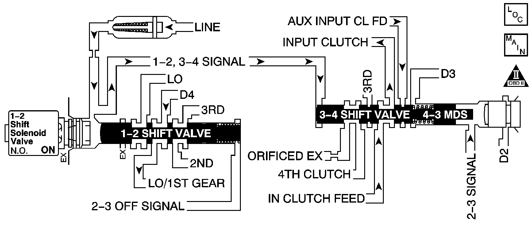
Circuit Description
The 1-2 shift solenoid (1-2 SS) valve is supplied with fused ignition voltage. The ground path is controlled by the PCM. When the PCM commands the solenoid OFF, a ground path is not provided and the filtered line pressure that is fed to the solenoid is exhausted. When the PCM commands the solenoid ON, a ground path is provided and the exhaust port is blocked, stopping the exhaust of line pressure.
The PCM identifies a 1-2 SS valve condition by monitoring the commanded gear versus gear ratio. Refer to Shift Solenoid Valve State and Gear Ratio .
If the PCM detects a 1st gear ratio when 2nd gear is commanded and a 4th gear ratio when 3rd gear is commanded, then DTC P0752 sets. DTC P0752 is a type B DTC.
DTC Descriptor
This diagnostic procedure supports the following DTC:
DTC P0752 1-2 Shift Solenoid Valve Performance - No Second or Third Gear
Conditions for Running the DTC
| • | No TP sensor DTC P0121, P0122 or P0123. |
| • | No VSS DTC P0502 or P0503. |
| • | No AT ISS sensor DTC P0716 or P0717. |
| • | No TCC system stuck ON DTC P0742. |
| • | No 1-2 SS valve electrical DTC P0753. |
| • | No 2-3 SS valve electrical DTC P0758. |
| • | No TCC PWM solenoid valve DTC P2761. |
| • | The engine speed is greater than 500 RPM for 5 seconds and not in fuel cut off. |
| • | The transmission fluid temperature is 20-130°C (68-266°F). |
| • | The transmission ISS is 150 RPM or more. |
| • | The transmission OSS is 300 RPM or more. |
| • | The time since the last gear range change is greater than 1 second. |
| • | The TP angle is greater than 10 percent. |
| • | The engine torque is 27-270 N·m (20-200 lb ft). |
Conditions for Setting the DTC
The following conditions both occur twice in one trip:
| • | The PCM commands 2nd gear and the gear ratio indicates 1st gear, 2.87:1 to 2.97:1, for 1 second. |
| • | The PCM commands 3rd gear and the gear ratio indicates 4th gear, 0.65:1 to 0.75:1, for 1 second. |
Action Taken When the DTC Sets
| • | The PCM illuminates the malfunction indicator lamp (MIL) during the second consecutive trip in which the Conditions for Setting the DTC are met. |
| • | The PCM commands maximum line pressure. |
| • | The PCM inhibits 3-2 downshifts when the vehicle speed is greater than 48 km/h (30 mph). |
| • | The PCM freezes transmission adaptive functions. |
| • | The PCM records the operating conditions when the Conditions for Setting the DTC are met. The PCM stores this information as Freeze Frame and Failure Records. |
| • | The PCM stores DTC P0752 in PCM history during the second consecutive trip in which the Conditions for Setting the DTC are met. |
Conditions for Clearing the MIL/DTC
| • | The PCM turns OFF the MIL during the third consecutive trip in which the diagnostic test runs and passes. |
| • | A scan tool can clear the MIL/DTC. |
| • | The PCM clears the DTC from PCM history if the vehicle completes 40 warm-up cycles without an emission-related diagnostic fault occurring. |
| • | The PCM cancels the DTC default actions when the ignition switch is OFF long enough in order to power down the PCM. |
Diagnostic Aids
If DTC P0752 is cleared, then will not reset when the vehicle is driven, some of the following conditions may exist:
| • | Fluid contamination |
| • | Plugged fluid circuits |
| • | Restricted fluid circuits |
Test Description
The number below refers to the step number on the diagnostic table.
Step | Action | Value(s) | Yes | No | ||||||||||
|---|---|---|---|---|---|---|---|---|---|---|---|---|---|---|
1 | Did you perform the Diagnostic System Check - Vehicle? | -- | Go to Step 2 | Go to Diagnostic System Check - Vehicle in Vehicle DTC Information | ||||||||||
2 | Did you perform the Transmission Fluid Checking Procedure? | -- | Go to Step 3 | Go to Transmission Fluid Check | ||||||||||
Important: Before clearing the DTCs, use the scan tool in order to record the Freeze Frame and Failure Records for reference. Using the Clear DTC Information function will erase the stored Freeze Frame and Failure Records from the PCM. Did the gear ratios indicate a 1-1-4-4 shift pattern? | 1st: 2.87:1 to 2.97:1 2nd: 1.52:1 to 1.62:1 3rd: 0.95:1 to 1.05:1 4th: 0.65:1 to 0.75:1 | Go to Step 4 | Go to Diagnostic Aids | |||||||||||
4 | Inspect the 1-2 shift solenoid valve/hydraulic circuit for the following conditions:
Refer to:
Did you find and correct the condition? | -- | Go to Step 5 | -- | ||||||||||
5 | Perform the following procedure in order to verify the repair:
Has the test run and passed? | 1st: 2.87:1 to 2.97:1 2nd: 1.52:1 to 1.62:1 3rd: 0.95:1 to 1.05:1 4th: 0.65:1 to 0.75:1 | Go to Step 6 | Go to Step 2 | ||||||||||
6 | With a scan tool, observe the stored information, capture info and DTC info. Does the scan tool display any DTCs that you have not diagnosed? | -- | Go to Diagnostic Trouble Code (DTC) List - Vehicle in Vehicle DTC Information | System OK |
