Inside Rearview Mirror Replacement DD7
Removal Procedure
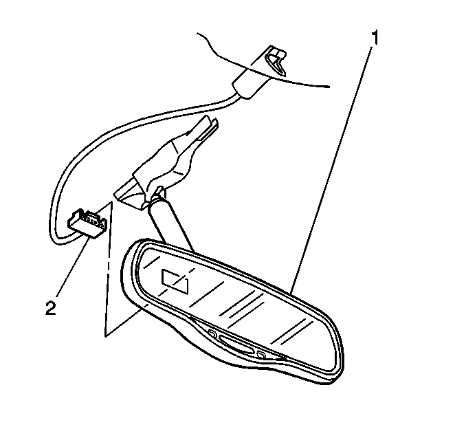
- Disconnect the electrical connectors (2) at the rear of the mirror assembly.
- Twist the mirror to one side and use one hand in order to support the edge of the mirror against the windshield. Using the other hand, pull the mirror away from the windshield with a quick jerk.
Notice: Do not use tools or other objects to pry the mirror mount or the mirror away from the windshield. Using tools may damage the mirror mount, the mirror or the windshield.

Installation Procedure
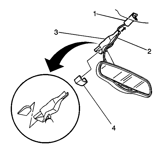
- Position the bottom of the mirror base (3) against the windshield at the top of the support.
- Slide the base onto the support keeping the base parallel to the windshield.
- As the base starts to engage, apply force against the base while maintaining a downward force until it snaps onto the support with an audible click. This operation will require at least 89 N (20 lb) of force.
- Ensure that the mirror is securely attached to the support by adjusting the mirror in a normal up/down and side to side range.
- Connect the electrical connector (2) into the electrical cavity in the back of the mirror (1). An audible click should be heard in order to indicate the proper installation of the connector.
- Perform the compass calibration and variance set up procedure.


Inside Rearview Mirror Replacement UE1
Removal Procedure
- Disconnect the electrical connector from the back of the mirror.
- Adjust the mirror to the full upward position.
- Using a flat bladed tool, remove the set screw trim cover on the mirror base.
- Loosen the set screw in order to remove the mirror from the button assembly.
- Slide the mirror assembly in an upward motion in order to remove.

Installation Procedure
- Position the center bottom of the mirror mount against the windshield at the top of the support button.
- Slide the base of the mirror onto the button.
- Install the mirror base trim cover.
- Connect the electrical connector.
- Reposition the mirror assembly.
- Preform the compass variance setup procedure.

Notice: Use the correct fastener in the correct location. Replacement fasteners must be the correct part number for that application. Fasteners requiring replacement or fasteners requiring the use of thread locking compound or sealant are identified in the service procedure. Do not use paints, lubricants, or corrosion inhibitors on fasteners or fastener joint surfaces unless specified. These coatings affect fastener torque and joint clamping force and may damage the fastener. Use the correct tightening sequence and specifications when installing fasteners in order to avoid damage to parts and systems.
Tighten
Tighten the set screw to 1.8 N·m (16 lb in)
in order to secure the mirror base to the button.
