For 1990-2009 cars only
Front Wheel Speed Sensor Wiring Harness Replacement Left
Removal Procedure
- Turn OFF the ignition.
- Raise and support the vehicle. Refer to Lifting and Jacking the Vehicle in General Information.
- Remove the left front tire and wheel assembly. Refer to Tire and Wheel Removal and Installation in Tires and Wheels.
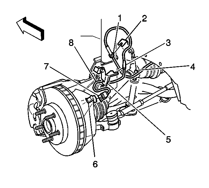
- Remove the wheel speed sensor connector (7) from the wheel speed sensor (6).
- Remove the harness grommet (3) from the strut bracket (5).
- Remove the harness grommet (1) from the rail bracket (2).
- Remove the harness clip (4) from the rail bracket (2).
- Route the wheel speed sensor wiring (8) through the top of the engine compartment.
- Lower the vehicle. Refer to Lifting and Jacking the Vehicle in General Information.
- Remove the master cylinder from the brake booster and carefully position the master cylinder out of the way. Refer the Master Cylinder Replacement in Hydraulic Brake.
- Remove the washer solvent reservoir and carefully position out of the way. Refer to Washer Pump/Reservoir Replacement in Wiper/Washer System.
- Cut the engine harness conduit to locate the 2 heat shrink sealed splices.

Important: The wheel speed sensor wiring is included in the engine harness. The wiring between the wheel speed sensor and the heat shrink sealed splices is high-flex cable and must not be repaired or spliced. This procedure replaces the high-flex cable with a jumper harness from a supplied repair kit.
Installation Procedure
- Replace the wheel speed sensor jumper harness. Refer to Wiring Repairs in Wiring Systems.
- Route the wheel speed sensor jumper through the engine compartment to the wheel well.
- Install the washer solvent reservoir. Refer to Washer Pump/Reservoir Replacement in Wipers/Washer Systems.
- Install the master cylinder to the brake booster. Refer to Master Cylinder Replacement in Hydraulic Brake.
- Raise the vehicle. Refer to Lifting and Jacking the Vehicle in General Information.
- Install the wheel speed sensor connector (7) to the wheel speed sensor (6).
- Install the harness grommet (3) to the strut bracket (5).
- Install the harness grommet (1) to the rail bracket (2).
- Install the harness clip (4) the rail bracket (2).
- Install the left front tire and wheel assembly. Refer to Tire and Wheel Removal and Installation in Tires and Wheels.
- Lower the vehicle. Refer to Lifting and Jacking the Vehicle in General Information.
- Perform the ABS Diagnostic System Check. Refer to Diagnostic System Check - ABS .

Front Wheel Speed Sensor Wiring Harness Replacement Right
Removal Procedure
- Turn OFF the ignition.
- Raise and support the vehicle. Refer to Lifting and Jacking the Vehicle in General Information.
- Remove the wheel speed sensor connector (7) from the wheel speed sensor (6).
- Remove the harness grommet (3) from the strut bracket (5).
- Remove the harness grommet (1) from the rail bracket (2).
- Remove the harness clip (4) from the rail bracket (2).
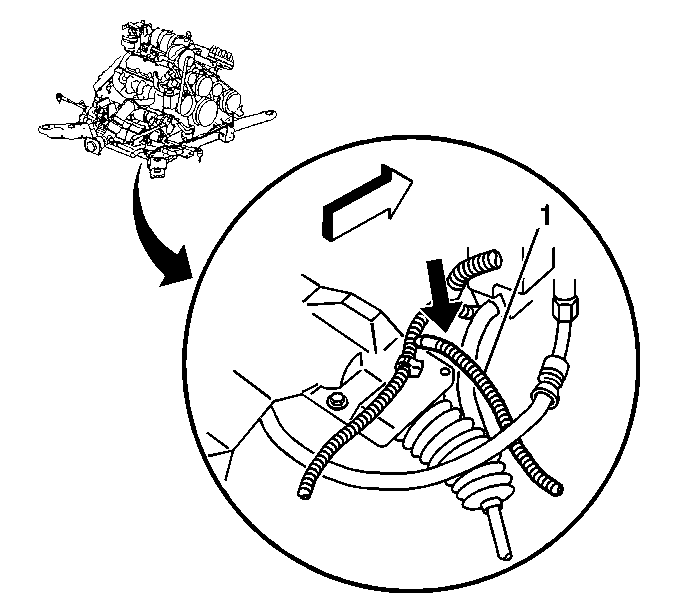
- Cut the engine harness conduit (1) at the indicated location.

Important: The wheel speed sensor wiring is included in the engine harness. The wiring between the wheel speed sensor and the heat shrink sealed splices is high-flex cable and must not be repaired or spliced. This procedure replaces the high-flex cable with a jumper harness from a supplied repair kit.

Installation Procedure
- Replace the wheel sped sensor jumper harness. Refer to Wiring Repairs in Wiring Repair.
- Route the wheel speed sensor jumper through the engine compartment to the wheel well.
- Install the wheel speed sensor connector (7) to the wheel speed sensor (6).
- Install the harness grommet (3) to the strut bracket (5).
- Install the harness grommet (1) to the rail bracket (2).
- Install the harness clip (4) to the rail bracket (2).
- Lower the vehicle. Refer to Lifting and Jacking the Vehicle in General Information.
- Perform the ABS Diagnostic System Check. Refer to Diagnostic System Check - ABS .

