Tools Required
J 39400-A Halogen Leak Detector
Removal Procedure
Important: When replacing a failed compressor it will be necessary to inspect the orifice tube for material build up. Clean or replace as necessary. Refer to Expansion (Orifice) Tube Replacement .
- Recover the refrigerant. Refer to Refrigerant Recovery and Recharging .
- Remove the accessory drive belt. Refer to Drive Belt Replacement or Drive Belt Replacement in Engine Mechanical.
- Raise and support the vehicle. Refer to Lifting and Jacking the Vehicle in General Information.
- Remove the right front wheelhouse filler. Refer to Wheelhouse Filler Replacement in Body Front End.
- Remove the lower air deflector. Refer to Front Air Deflector Replacement in Body Front End.
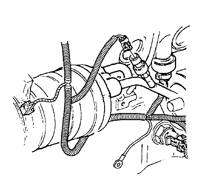
- Remove the wiring harness bracket bolt.
- Disconnect the electrical connector from the compressor.
- Disconnect the electrical connector from the A/C pressure sensor.
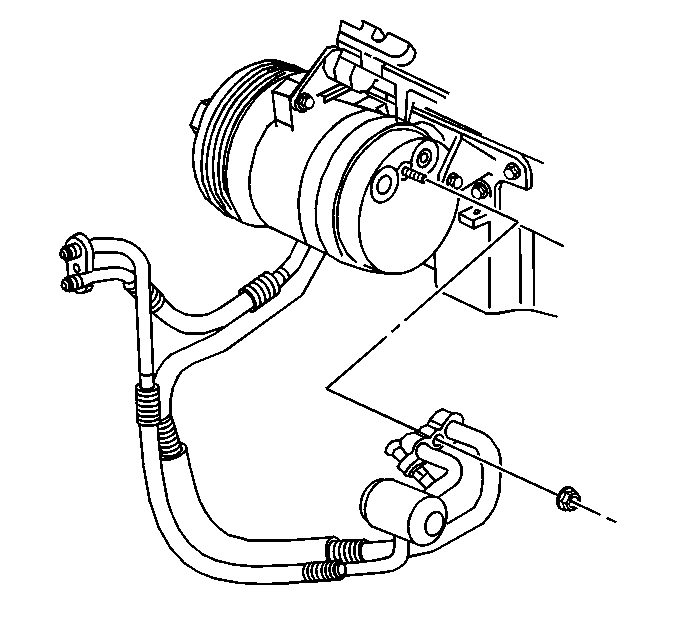
- Remove the A/C compressor hose from the compressor.
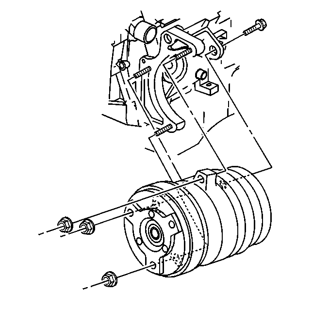
- Remove the front compressor mounting nuts.
- Remove the bolt from the rear of the compressor.
- Remove the compressor.
- If replacing the compressor, drain and measure as much of the oil as possible from the removed compressor:


| 13.1. | Drain the oil from both the suction and discharge ports of the removed compressor into a clean container. |
| 13.2. | Remove the compressor crankcase oil drain plug and drain the crankcase oil into the same container. |
| 13.3. | Measure and record the amount of oil drained from the removed compressor. |
This measurement will be used during installation of the replacement compressor.
| 13.4. | Properly dispose the used PAG oil. |
Installation Procedure
Important: When servicing or replacing the compressor, drain and measure the oil from the old compressor. If less than 1 fluid ounce is drained, add 2 ounces to the replacement compressor. If 1 ounce or more is drained, fill the compressor with that amount.
- Install the compressor.
- Install the mounting nuts and the bolt.
- Install the rear bolt to the compressor.
- Install the A/C compressor hose to the compressor.
- Install the wiring harness bracket and bolt.
- Connect the electrical connections to the compressor.
- Connect the electrical connection to the A/C pressure sensor.
- Lower the vehicle.
- Install the accessory drive belt. Refer to Drive Belt Replacement or Drive Belt Replacement in Engine Mechanical.
- Recharge the A/C system. Refer to Refrigerant Recovery and Recharging .
- Leak test the component fittings using theJ 39400-A .
- Install the lower air deflector. Refer to Front Air Deflector Replacement in Body Front End.
- Install the right front fascia extension. Refer to Wheelhouse Filler Replacement in Body Front End.

Notice: Use the correct fastener in the correct location. Replacement fasteners must be the correct part number for that application. Fasteners requiring replacement or fasteners requiring the use of thread locking compound or sealant are identified in the service procedure. Do not use paints, lubricants, or corrosion inhibitors on fasteners or fastener joint surfaces unless specified. These coatings affect fastener torque and joint clamping force and may damage the fastener. Use the correct tightening sequence and specifications when installing fasteners in order to avoid damage to parts and systems.
Tighten
Tighten the nuts to 50 N·m (37 lb ft).
Tighten
Tighten the bolt to 50 N·m (37 lb ft).

Tighten
Tighten the nut to 30 N·m (22 lb ft).
Tighten
Tighten the bolt to 12 N·m (106 lb in).

