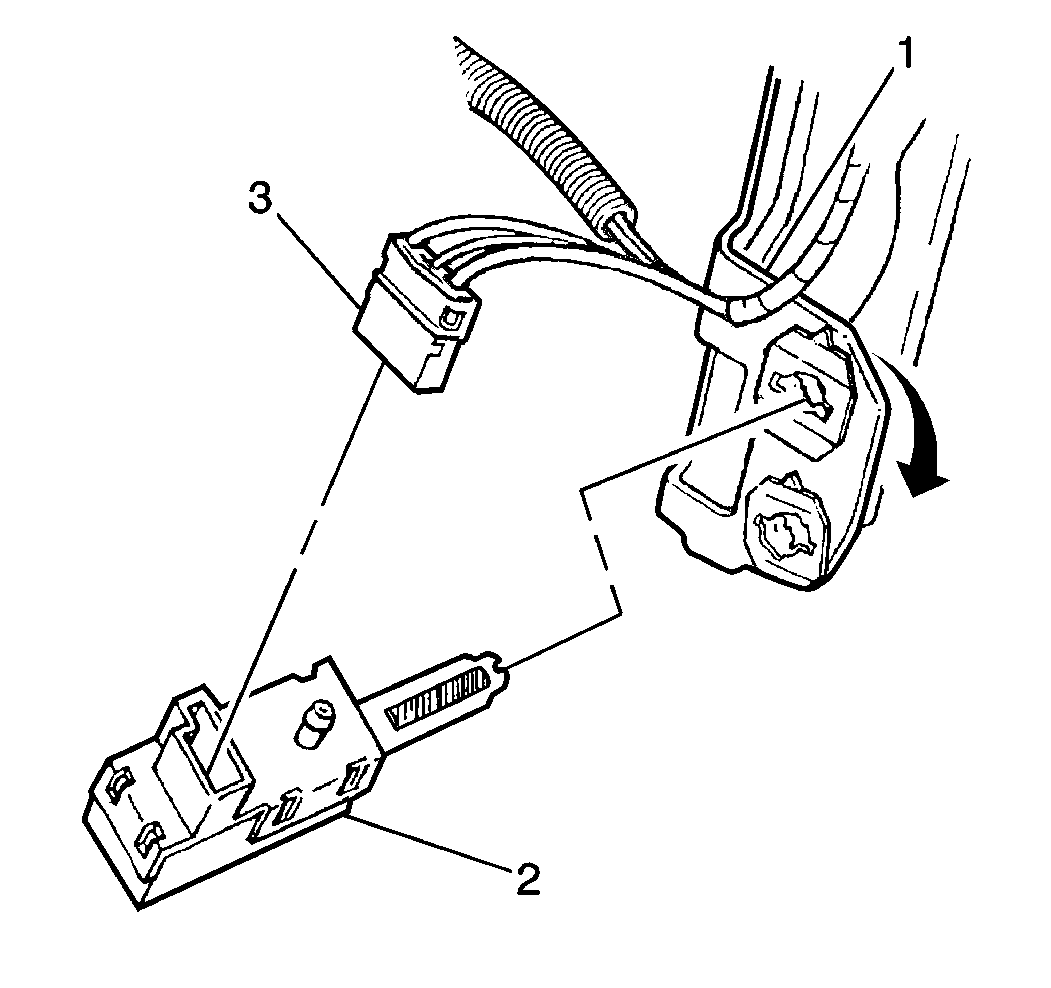
For 1990-2009 cars only
Removal Procedure
- Remove the lefthand IP sound insulator.
- Disconnect the stoplamp/BTSI switch.
- Disconnect the TCC. ABS switch.
- Twist the switch (2) counterclockwise to unlock and pull out of the retainer.
- Remove the electrical connectors (3) from the switch.

Installation Procedure
- Install the TCC/ABS Switch (2).
- Slide the switch (2) (with all connections (3) made) into the retainer.
- Press the switch in until the switch plunger is fully depressed into the switch barrel.
- Twist the switch clockwise until the travel stop has been reached (approximately 60 degrees).
- With the switch fully locked, the electrical connector will face the 3 o'clock position.
- Install the lefthand IP sound insulator.
Notice: Do not push or pull on the brake pedal while installing the brake switches or installing the brake switches or damage to the brake system and/or switch may occur.
Notice: Do not side load the brake switches during installation or damage to the brake system and/or switches may occur.
Important: Make all connections before installing. Be sure all connectors are firmly seized and locked.

