| Table 1: | A/C Clutch |
| Table 2: | A/C Pressure Sensor |
| Table 3: | Air Inlet Actuator |
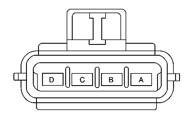
| Table 4: | Ambient Air Temperature Sensor |
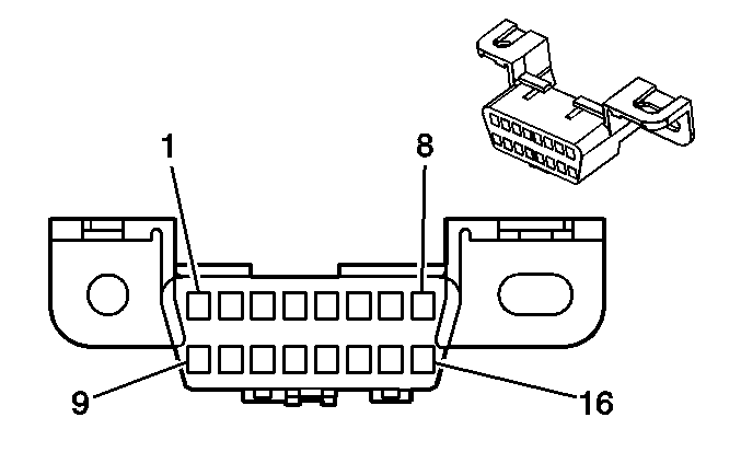
| Table 5: | Blower Control Module |
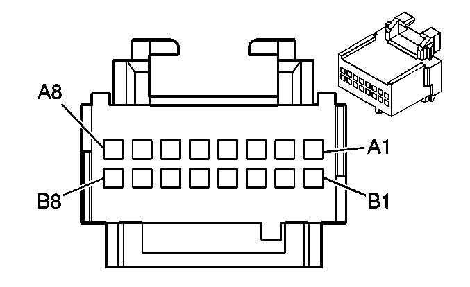
| Table 6: | Data Link Connector (DLC) |
| Table 7: | Driver Air Mix Actuator |
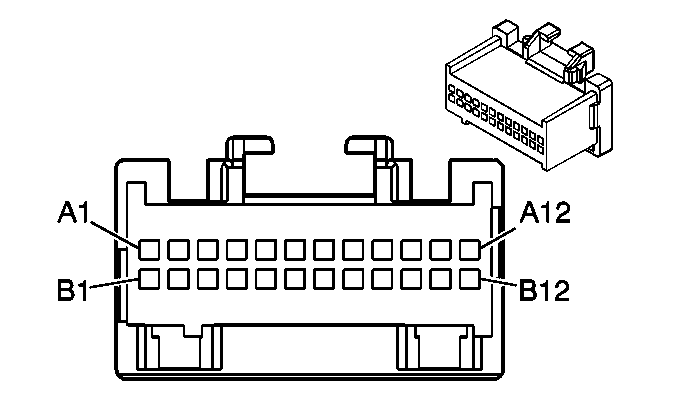
| Table 8: | Heater and A/C Control |
| Table 9: | Heater and A/C Programmer C1 |
| Table 10: | Heater and A/C Programmer C2 |
| Table 11: | Heater Temperature Sensor, Left Side |
| Table 12: | Left A/C Temperature Sensor |
| Table 13: | Right A/C Temperature Sensor |
| Table 14: | Left Sun Load Temperature Sensor |
| Table 15: | Mode Actuator |
| Table 16: | Passenger Air Mix Actuator |
| Table 17: | Passenger Climate Control |
| Table 18: | Heater Temperature Sensor, Right Side |
| Table 19: | Inside Air Temperature Sensor |
| Table 20: | Right Sun Load Temperature Sensor |
| |||||||
|---|---|---|---|---|---|---|---|
Connector Part Information |
| ||||||
Pin | Wire Color | Circuit No. | Function | ||||
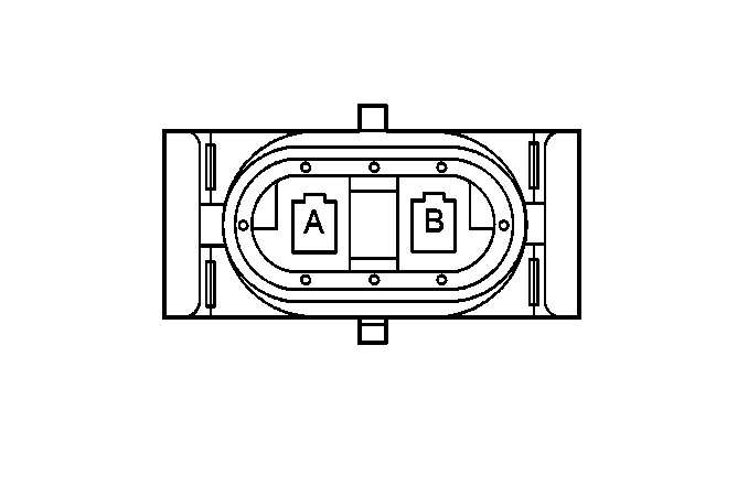
A | DK GRN | 59 | A/C Clutch Solenoid Feed | ||||
B | BLK | 50 | Ground | ||||
| |||||||
|---|---|---|---|---|---|---|---|
Connector Part Information |
| ||||||
Pin | Wire Color | Circuit No. | Function | ||||
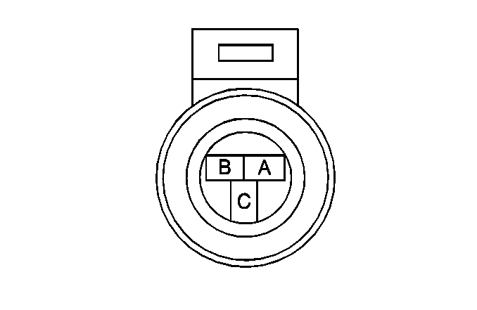
A | BLK | 452 | Sensor Return | ||||
B | GRY | 474 | 5 Volt Reference | ||||
C | RED/BLK | 380 | A/C Pressure Sensor Signal | ||||
| |||||||
|---|---|---|---|---|---|---|---|
Connector Part Information |
| ||||||
Pin | Wire Color | Circuit No. | Function | ||||
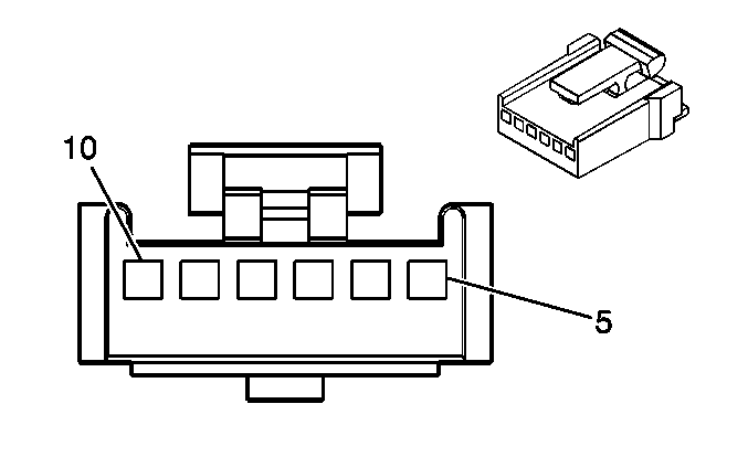
5 | BRN | 41 | Fused Output (Ignition) | ||||
6 | BRN/WHT | 1218 | Mode Valve Motor Feed - Upper | ||||
7 | YEL | 1791 | Air Temperature Valve Motor Return | ||||
8 | -- | -- | Not Used | ||||
9 | RED | 708 | Mode Valve Position Sensor Signal-Upper | ||||
10 | GRY | 705 | 5 Volt Reference | ||||
| |||||||
|---|---|---|---|---|---|---|---|
Connector Part Information |
| ||||||
Pin | Wire Color | Circuit No. | Function | ||||
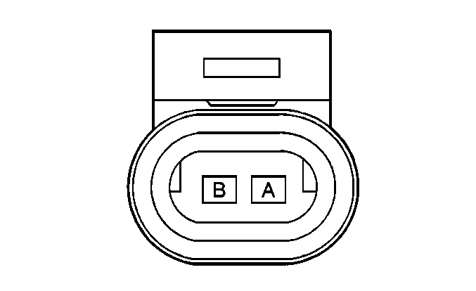
A | LT GRN/BLK | 735 | Outside Ambient Temperature Sensor Signal | ||||
B | YEL | 61 | Outside Ambient Temperature Sensor Signal | ||||
| |||||||
|---|---|---|---|---|---|---|---|
Connector Part Information |
| ||||||
Pin | Wire Color | Circuit No. | Function | ||||
A | BLK | 450 | Ground | ||||
B | RED | 242 | Fused Output (Battery) | ||||
C | GRY/BLK | 754 | Blower Speed Control (Signal) | ||||
D | -- | -- | Not Used | ||||
| |||||||
|---|---|---|---|---|---|---|---|
Connector Part Information |
| ||||||
Pin | Wire Color | Circuit No. | Function | ||||
1 | -- | -- | Not Used | ||||
2 | PPL | 1807 | Class 2 Serial Data Line | ||||
3 | -- | -- | Not Used | ||||
4 | BLK | 350 | Ground | ||||
5 | BLK/WHT | 351 | Ground | ||||
6-7 | -- | -- | Not Used | ||||
8 | BLK/WHT | 1455 | Keyless Entry Program Enable Signal | ||||
9-13 | -- | -- | Not Used | ||||
14 | DK GRN | 835 | E and C Serial Data Line | ||||
15 | -- | -- | Not Used | ||||
16 | ORN | 1140 | Fused Output (Battery) | ||||

| |||||||
|---|---|---|---|---|---|---|---|
Connector Part Information |
| ||||||
Pin | Wire Color | Circuit No. | Function | ||||
5 | BRN | 41 | Fused Output (Ignition) | ||||
6 | DK BLU | 1199 | Air Temperature Valve Motor Feed | ||||
7 | YEL | 1791 | Air Temperature Valve Motor Return | ||||
8 | -- | -- | Not Used | ||||
9 | LT BLU | 733 | Air Temperature Valve Position Sensor Signal | ||||
10 | GRY | 705 | 5 Volt Reference | ||||
| |||||||
|---|---|---|---|---|---|---|---|
Connector Part Information |
| ||||||
Pin | Wire Color | Circuit No. | Function | ||||
A1-A6 | -- | -- | Not Used | ||||
A7 | BRN | 341 | Fused Output - IGN | ||||
A8 | BLK/WHT | 351 | Ground | ||||
B1 | LT BLU | 1880 | HVAC Control Signal | ||||
B2 | PPL | 1881 | HVAC Control Signal | ||||
B3 | GRY | 8 | IP Lamp Feed | ||||
B4-B8 | -- | -- | Not Used | ||||
| |||||||
|---|---|---|---|---|---|---|---|
Connector Part Information |
| ||||||
Pin | Wire Color | Circuit No. | Function | ||||
A1 | GRY | 705 | 5 Volt Reference | ||||
A2 | DK GRN | 892 | Coolant Temperature Switch Feed | ||||
A3 | -- | -- | Not Used | ||||
A4 | RED | 708 | Mode Valve Position Sensor Signal - Upper | ||||
A5 | LT BLU | 733 | Air Temperature Valve Position Sensor Signal | ||||
A6 | DK BLU | 1646 | Air Temperature Valve Position Sensor Signal - Passenger | ||||
A7 | YEL | 1791 | Air Temperature Valve Motor Return | ||||
A8 | YEL | 1318 | Mode Valve Motor Feed - Lower | ||||
A9 | -- | -- | Not Used | ||||
A10 | BRN/WHT | 1218 | Mode Valve Motor Feed - Upper | ||||
A11 | DK BLU | 1199 | Air Temperature Valve Motor Feed | ||||
A12 | WHT/BLK | 1236 | Air Temperature Valve Motor Feed - Passenger | ||||
B1 | LT GRN/BLK | 735 | Outside Ambient Temperature Sensor Signal | ||||
B2 | LT BLU/BLK | 590 | Dirver Solar Sensor Signal | ||||
B3 | GRY | 1548 | Passenger Solar Sensor Signal | ||||
B4 | DK GRN | 734 | Inside Temperature Sensor Signal | ||||
B5 | DK BLU/ WHT | 831 | HVAC Control Assembly Signal - Passenger | ||||
B6 | BLK | 516 | Air Temperature Sensor Signal - A/C Left | ||||
B7 | TAN | 517 | Air Temperature Sensor Signal - A/C Right | ||||
B8 | YEL | 61 | Outside Ambient Temperature Sensor Return | ||||
B9 | BLK | 518 | Air Temperature Sensor Signal - Left Heater | ||||
B10-B12 | -- | -- | Not Used | ||||
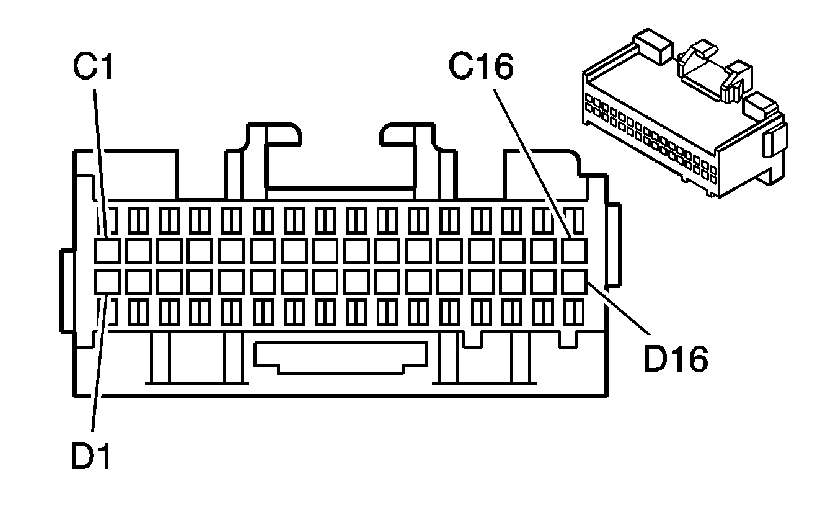
| |||||||
|---|---|---|---|---|---|---|---|
Connector Part Information |
| ||||||
Pin | Wire Color | Circuit No. | Function | ||||
C1 | ORN | 840 | Fused Output - Battery | ||||
C2 | BRN | 341 | Fused Output - IGN | ||||
C3 | -- | -- | Not Used | ||||
C4 | DK GRN | 835 | E and C Serial Data Line | ||||
C5-C6 | -- | -- | Not Used | ||||
C7 | PPL | 1807 | Class 2 Serial Data Line | ||||
C8 | PPL | 1807 | Class 2 Serial Data Line | ||||
C9-C11 | -- | -- | Not Used | ||||
C12 | LT BLU | 1880 | HVAC Control Signal - Driver | ||||
C13 | PPL | 1881 | HVAC Control Signal - Clock- Driver | ||||
C14 | -- | -- | Not Used | ||||
C15 | TAN | 1812 | HVAC Control Return - Passenger | ||||
C16 | -- | -- | Not Used | ||||
D1-D2 | -- | -- | Not Used | ||||
D3 | BLK | 520 | Air Temperature Sensor Signal - Right Heater | ||||
D4-D5 | -- | -- | Not Used | ||||
D6 | BLK | 291 | HVAC Control Lamp Feed - Passenger | ||||
D7-D10 | -- | -- | Not Used | ||||
D11 | GRY/BLK | 754 | Blower Speed Signal - Speed Control | ||||
D12-D13 | -- | -- | Not Used | ||||
D14 | PPL/WHT | 724 | Vacuum Flourescent Dimming Signal | ||||
D15 | -- | -- | Not Used | ||||
D16 | BLK/WHT | 351 | Ground | ||||
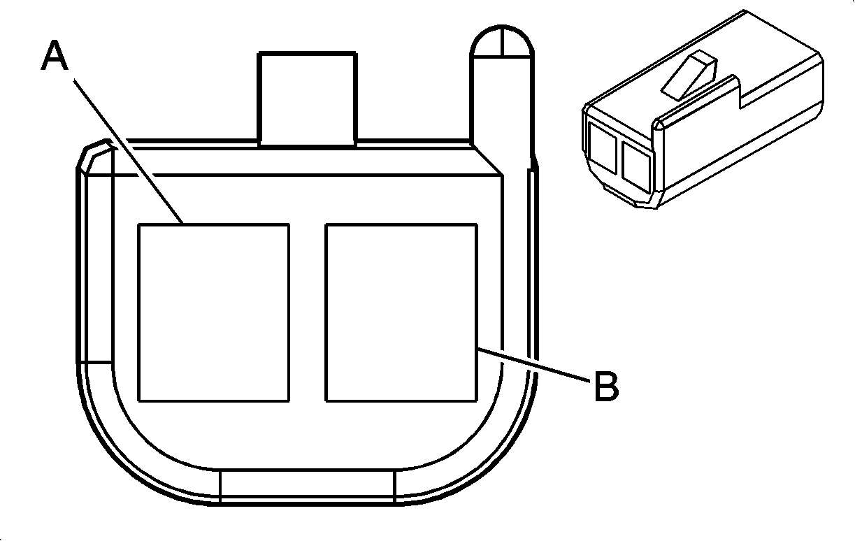
| |||||||
|---|---|---|---|---|---|---|---|
Connector Part Information |
| ||||||
Pin | Wire Color | Circuit No. | Function | ||||
A | BLK | 518 | Heater Temperature Sensor Signal, Left Side | ||||
B | YEL | 61 | Sensor Return | ||||

| |||||||
|---|---|---|---|---|---|---|---|
Connector Part Information |
| ||||||
Pin | Wire Color | Circuit No. | Function | ||||
A | BLK | 516 | Air Temperature Sensor Signal-A/C Left | ||||
B | YEL | 61 | Outside Ambient Air Temperature Sensor Return | ||||

| |||||||
|---|---|---|---|---|---|---|---|
Connector Part Information |
| ||||||
Pin | Wire Color | Circuit No. | Function | ||||
A | TAN | 517 | Air Temperature Sensor Signal - A/C Right | ||||
B | YEL | 61 | Outside Ambient Air Temperature Sensor Return | ||||
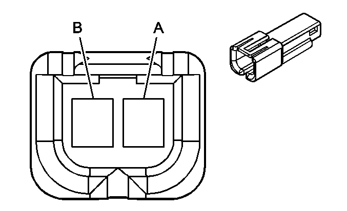
| |||||||
|---|---|---|---|---|---|---|---|
Connector Part Information |
| ||||||
Pin | Wire Color | Circuit No. | Function | ||||
A | LT BLU/ BLK | 590 | Solar Sensor Signal-Driver | ||||
B | YEL | 61 | Outside Ambient Temperature Sensor Return | ||||

| |||||||
|---|---|---|---|---|---|---|---|
Connector Part Information |
| ||||||
Pin | Wire Color | Circuit No. | Function | ||||
5 | BRN | 41 | Fused Output (Ignition) | ||||
6 | LT GRN | 1318 | Mode Valve Motor Feed-Lower | ||||
7 | YEL | 1791 | Air Temperature Valve Motor Return | ||||
8 | -- | -- | Not Used | ||||
9 | YEL/BLK | 892 | Coolant Temperature Switch Feed | ||||
10 | GRY | 705 | 5 Volt Reference | ||||

| |||||||
|---|---|---|---|---|---|---|---|
Connector Part Information |
| ||||||
Pin | Wire Color | Circuit No. | Function | ||||
5 | BRN | 41 | Fused Output (Ignition) | ||||
6 | WHT/BLK | 1236 | Air Temperature Valve Motor Feed-Passenger | ||||
7 | YEL | 1791 | Air Temperature Valve Motor Return | ||||
8 | -- | -- | Not Used | ||||
9 | DK BLU | 1646 | Air Temperature Valve Position Sensor Signal-Passenger | ||||
10 | GRY | 705 | 5 Volt Reference | ||||

| |||||||
|---|---|---|---|---|---|---|---|
Connector Part Information |
| ||||||
Pin | Wire Color | Circuit No. | Function | ||||
5 | GRY | 8 | IP Lamp Feed | ||||
6 | -- | -- | Not Used | ||||
7 | BLK | 351 | Ground | ||||
8 | TAN | 1812 | HVAC Control Return, Passenger | ||||
9 | BLK | 291 | HVAC Control Assembly Lamp Feed-Passenger | ||||
10 | DK BLU/ WHT | 831 | HVAC Control Signal, Passenger | ||||

| |||||||
|---|---|---|---|---|---|---|---|
Connector Part Information |
| ||||||
Pin | Wire Color | Circuit No. | Function | ||||
A | BLK | 520 | A/C Air Temperature Sensor Signal, Right Side | ||||
B | YEL | 61 | Outside Ambient Air Temperature Sensor Return | ||||
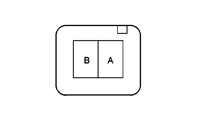
| |||||||
|---|---|---|---|---|---|---|---|
Connector Part Information |
| ||||||
Pin | Wire Color | Circuit No. | Function | ||||
A | DK GRN | 734 | Inside Temperature Sensor Signal | ||||
B | YEL | 61 | Outside Ambient Air Temperature Sensor Return | ||||

| |||||||
|---|---|---|---|---|---|---|---|
Connector Part Information |
| ||||||
Pin | Wire Color | Circuit No. | Function | ||||
A | GRY | 1548 | Solar Sensor Signal-Passenger | ||||
B | YEL | 61 | Outside Ambient Temperature Sensor Return | ||||
