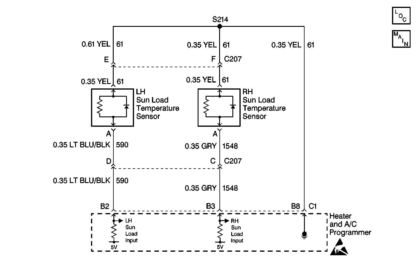
Circuit Description
The left sun load temperature sensor is a light sensitive photodiode that controls signal voltage to the HVAC control module (HCM). This photodiode is different from standard thermistor sensors and resistance measurements will not produce accurate results. The HCM monitors voltage on CKT 590 to the sensor. When the sensor is in direct sun light, the HCM reads a low signal voltage at terminal B2, connector C2. When the sensor is shaded, the signal voltage increases. Signal voltage will vary from 5 V (open circuit) to 0 V (short circuit).
Conditions for Setting the DTC
| • | The ignition is ON. |
| • | The circuit is open or shorted. |
Action Taken When the DTC Sets
| • | The HCM will default the system to dark or no sun load value. |
| • | The default valve allows the system to operate. |
Conditions for Clearing the DTC
| • | Use a Scan Tool . |
| • | A history DTC will clear after 50 consecutive ignition cycles have occurred without a malfunction. |
| • | SBM battery voltage is interrupted. |
Test Description
The numbers below refer to the step numbers on the diagnostic table.
-
Perform the Body Control Module (SBM) Diagnostic System Check before continuing with the diagnosis of this DTC.
-
This step determines whether the sensor is operational.
-
This step determines that the DTC was not set in error.
-
This step determines if the malfunction is the sensor or an open or a short in a circuit.
-
This step determines if the heater and A/C programmer or an open or a short is causing the malfunction.
-
The Scan Tool tests for proper sensor operation. Clear all the DTC's after the repair procedures are complete.
Step | Action | Value(s) | Yes | No |
|---|---|---|---|---|
Did you perform the BCM Diagnostic System Check? | -- | Go to Step 2 | Go to Diagnostic System Check - Body Control System in Body Control System | |
Did the sensor counts increase from the noted value? | -- | Go to Step 3 | Go to Step 4 | |
Did the DTC reset? | -- | Go to Step 4 | ||
Does the voltage equal the specified value? | 4.5-5.5 V | Go to Step 8 | Go to Step 5 | |
5 | Measure the voltage between the sun load temperature sensor harness connector terminal A and ground. Refer to Measuring Voltage in Wiring Systems. Does the voltage equal the specified value? | 4.5-5.5 V | Go to Step 9 | Go to Step 6 |
6 | Measure the voltage between the heater and A/C programmer terminal B2 and ground. Refer to Measuring Voltage in Wiring Systems. Does the voltage equal the specified value? | 4.5-5.5 V | Go to Step 7 | Go to Step 10 |
7 | Repair an open or a short in CKT 590 (GRY). Refer to Wiring Repairs in Wiring Systems. Is the repair complete? | -- | Go to Step 12 | -- |
8 | Replace the left sun load temperature sensor. Refer to Sun Load Sensor Replacement . Is the repair complete? | -- | Go to Step 12 | -- |
Are all of the HVAC sensor DTCs present? | -- | Go to Step 10 | Go to Step 11 | |
10 |
Is the repair complete? | -- | Go to Step 12 | -- |
11 | Repair an open or a short in CKT 61 (YEL). Refer to Wiring Repairs in Wiring Systems. Is the repair complete? | -- | Go to Step 12 | -- |
Is the system operating properly? | -- | -- |
