Removal Procedure
Tools Required
J 42640 Steering
Column Antirotation Pin

Caution: When performing service on or around SIR components or SIR wiring, follow
the procedure to temporarily disable SIR system. Refer to Disabling/Enabling
SIR System in Restraints. Failure to follow procedures could result in possible
air bag deployment, personal injury or otherwise unneeded SIR repairs.
Caution: This vehicle is equipped with a Supplemental Inflatable Restraint (SIR) System. Failure to follow the correct procedure could cause the following conditions:
| • | Unnecessary SIR system repairs |
| • | Refer to SIR Component Views in order to determine if you are performing service on or near the SIR components or the SIR wiring. |
| • | If you are performing service on or near the SIR components or the SIR wiring, disable the SIR system. Refer to Disabling the SIR System. |
- Disable
the SIR System. Refer to
Disabling the SIR System
in Restraints.

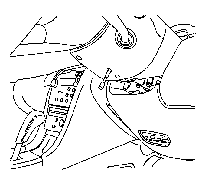
- Insert the J 42640
into the steering column access hole
in order to lock the steering column and in order to maintain correct orientation.
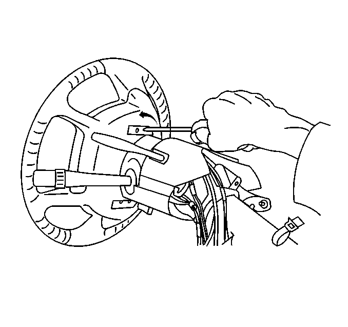
- Insert a flat-bladed screwdriver into one of the 4 openings
in the back of the steering wheel.
- Turn the screwdriver counterclockwise in order to disengage the
wire from the slot in the inflator module fastener.
- Repeat steps 2-4 for each of the 4 openings in the
back of the steering wheel.
- Gently pull the driver inflator module away from the steering
wheel.

Important: Observe the following routing positions for correct reassembly:
| • | The driver inflator wire routing positions |
| • | The redundant control wire routing positions |
| • | The horn wire routing positions |
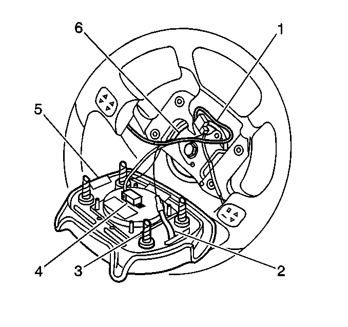
- Disconnect the following components:
| • | The connector position assurance (CPA) |
| • | The driver inflator module electrical connector |
- Remove the horn ground lead (2) from the threaded hole
in the steering wheel (6).
- Rotate the horn contact lead counterclockwise 1/4 turn.
- Remove the horn contact lead from the steering column cam tower.
- Remove the inflatable restraint steering wheel module (5).
Installation Procedure

Caution: When carrying a live inflator module, make sure the bag opening is pointed
away from you. Never carry the inflator module by the wires or connector on
the side of the module. In case of an accidental deployment, the bag will
then deploy with minimal chance of injury. When placing a live inflator module
on a bench or other surface, always face the bag up, away from the surface.
This is necessary so that a free space is provided to allow the air bag to
expand in the unlikely event of accidental deployment. Otherwise personal
injury may result.
- Install the horn ground lead (2) into the lower left threaded
hole in the steering wheel (6).
- Install the horn contact lead (2) into the steering column
cam tower.
- Rotate the horn contact 1/4 turn clockwise in order to
lock the contact.
- Connect the following components:
| • | The connector position assurance (CPA) |
| • | The driver inflator module electrical connector |
| | Important: Route the following wires correctly:
|
| • | The drive inflator wires |
| • | The redundant control wires |
- Align the driver inflator module fasteners to the steering column
fastener holes.
- Push the driver inflator module firmly into the steering column
in order to engage the fasteners.

- Remove the J 42640
from the steering column access hole.
- Enable the SIR system. Refer to
Enabling the SIR System
in Restraints


