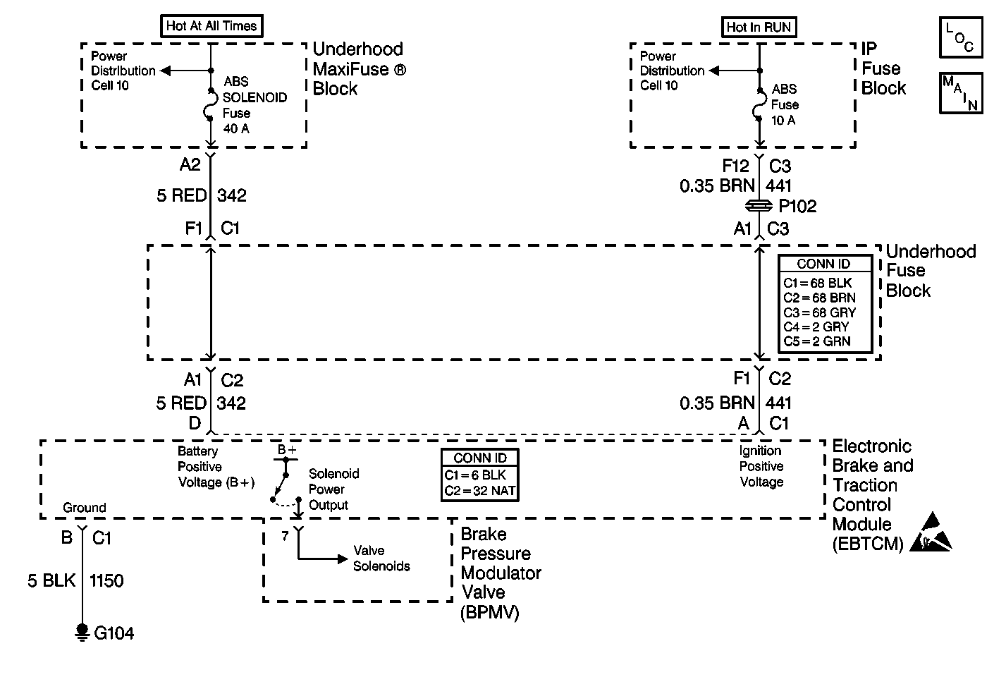
Circuit Description
The Class 2 serial data line allows all the modules on the line to transmit information to each other as needed. Each module is assigned an ID and all the information sent out on the line is assigned a priority by which it is received. When the ignition switch is turned to the RUN position each module begins to send and receive information. Each module on the Class 2 serial data line knows what information it needs to send out and what information it should be receiving. What the modules do not know is which module is supposed to send them the information. This information is only learned after the module has received the information it needs along with the ID of the module that sent the information. This information is then remembered until the ignition switch is turned off.
Step | Action | Value(s) | Yes | No |
|---|---|---|---|---|
DEFINITION: Scan tool can not communicate with the EBCM/EBTCM. | ||||
1 | Was the ABS Diagnostic System Check performed? | -- | Go to Diagnostic System Check | |
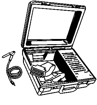
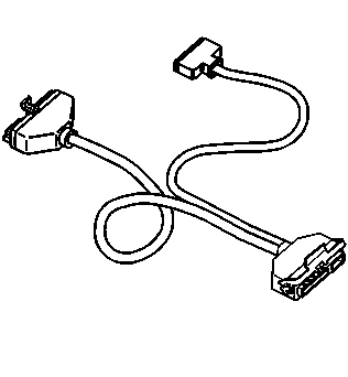
2 | Turn the ignition switch to the RUN position with the engine off. Can the scan tool communicate with other modules on the Class 2 serial data line, such as the PCM? | -- | Go to Scan Tool Does Not Communicate with Class 2 Data Line in Wiring Systems | |
3 | Inspect the 10A ABS SEN fuse in the IP fuse block. Is the fuse OK? | -- | ||
4 | Inspect the 40A ABS SOL fuse in the underhood maxifuse block. Is the fuse OK? | -- | ||
5 |
Is the fuse OK? | -- | Go to Diagnostic System Check | |
6 |
Is the resistance equal to the specified value? | OL (infinite) | ||
7 | Replace the EBCM/EBTCM. Refer to Electronic Brake Control Module Replacement . Is the replacement complete? | -- | Go to Diagnostic System Check | -- |
8 | Repair CKT 342 for a short to ground. Refer to Wiring Repairs in Wiring Systems. Is the repair complete? | -- | Go to Diagnostic System Check | -- |
9 |
Is the fuse OK? | -- | Go to Diagnostic System Check | |
10 |
Is the resistance equal to the specified value? | OL (infinite) | ||
11 | Repair CKT 441 for a short to ground. Refer to Wiring Repairs in Wiring Systems. Is the repair complete? | -- | Go to Diagnostic System Check | -- |
12 |
Is the voltage within the specified range? | Battery Voltage | Go to Wiring Repairs in Wiring Systems | |
13 | Using the J 39200 DMM, measure the voltage at the 40A ABS SOL fuse by probing between the fuse test terminals and a good ground. Is the voltage within the specified range? | Battery Voltage | Go to Wiring Repairs in Wiring Systems | |
14 |
Is the resistance less than specified value? | 2 ohms | ||
15 | Repair CKT 1150 or G104 for an open or high resistance. Refer to Wiring Repairs in Wiring Systems. Is the repair complete? | -- | Go to Diagnostic System Check | -- |
16 |
Is the voltage within the specified range? | Battery Voltage | ||
17 | Repair CKT 441 for an open. Refer to Wiring Repairs in Wiring Systems. Is the repair complete? | -- | Go to Diagnostic System Check | -- |
18 | Using the J 39200 DMM, measure the voltage between J 39700 terminals D and B. Is the voltage within the specified range? | Battery Voltage | ||
19 | Repair CKT 342 for an open. Refer to Wiring Repairs in Wiring Systems. Is the repair complete? | -- | Go to Diagnostic System Check | -- |
