For 1990-2009 cars only
Removal Procedure
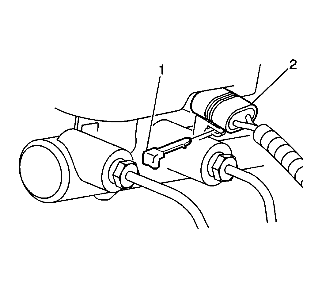
- Remove the electrical connector (2) from the fluid level sensor.
- Drain the brake fluid from the master cylinder reservoir.
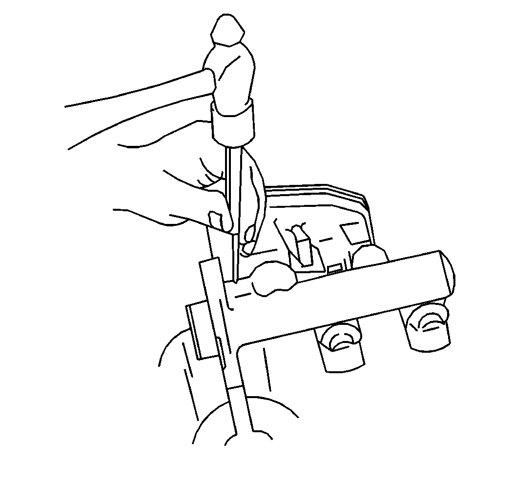
- Tap back the pins until clear of reservoir. Be careful not to damage the reservoir or master cylinder. If needed, loosen or remove the strut cross bar for access.
- Remove the reservoir.
- Remove the seals.
- Inspect the reservoir for cracks or deformities. If found, replace the reservoir.
- Clean the reservoir with clean denatured alcohol and dry the reservoir with unlubricated compressed air.


Installation Procedure
- Lubricate the new seals and the reservoir bayonets with clean brake fluid.
- Install the seals, making sure they are fully seated.
- Install the reservoir onto the master cylinder by pressing straight down by hand until pin holes are aligned.
- Tap in pins to retain reservoir. Be careful not to damage the reservoir or master cylinder. If strut cross bar had been loosened or removed, reinstall; refer to Front Suspension.
- Fill the master cylinder reservoir to full level mark using only Delco® Supreme II Brake fluid, or equivalent DOT 3 brake fluid (DOT 4 for Europe), as specified in Maintenance and Lubrication.
- Install the electrical connector (2) to fluid sensor, and secure with the retainer (1).
- Bleed the hydraulic system. Refer to Master Cylinder Bench Bleeding .


