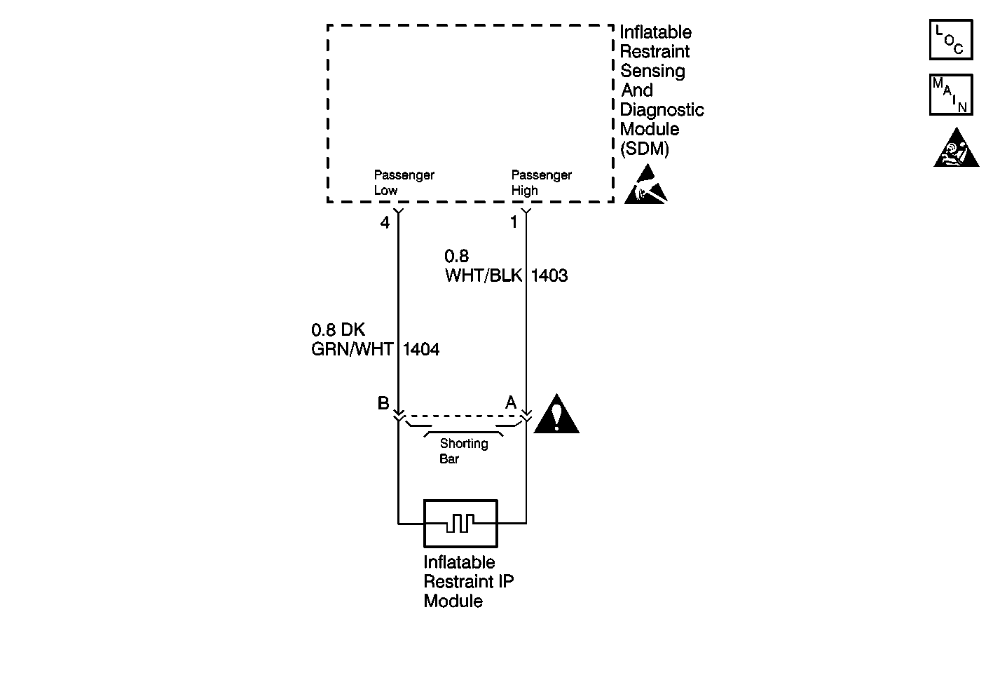
Circuit Description
When you first turn the ignition switch to the RUN position, the inflatable restraint sensing and diagnostic module (SDM) performs tests in order to diagnose critical malfunctions within itself. Upon passing these tests Ignition Positive Voltage, 23 VLR and the deployment loop voltages are measured in order to ensure they are within the normal voltage ranges. The SDM monitors the voltages at Driver Low terminal 3 and Passenger Low terminal 4 in order to detect shorts to ground in the inflator module circuits. The service wait time is 10 minutes. Refer to Disabling the SIR System or Enabling the SIR System .
Conditions for Setting the DTC
| • | The driver and passenger deployment loops are not open. |
| • | The driver deployment loop is not shorted to voltage. |
| • | The voltage at Driver Low terminal 3 is more than 3.3 volts. |
| • | The voltage at Passenger Low terminal 4 is less than 3.3 volts for 500 milliseconds. |
The following tests check for this DTC. These tests occur when Ignition 1 is within the normal operating voltage range.
| • | Power-On |
| When the malfunction is detected in this test, the Resistance Measurement test will not be performed. |
| • | Continuous Monitoring |
Action Taken When the DTC Sets
| • | The SDM sets DTC B1018 and also DTC B1071. |
| • | The SDM turns ON the AIR BAG warning lamp. |
Conditions for Clearing the MIL/DTC
DTC B1018 is a latched code. You cannot clear a latched code. Repair the malfunction that set this DTC before you replace the SDM.
Diagnostic Aids
A short to ground in the inflatable restraint IP module circuit may cause an intermittent condition. A DTC B1018 would be accompanied by DTC B1071. Carefully inspect CKT 1403 (WHT/BLK) and CKT 1404 (DK GRN/WHT) for cut or chafed wires. Wiring pigtail damage requires replacement of the inflatable restraint IP module. Carefully inspect the circuits and components indicated on the DTC B1018 table in order to prevent damage to the replacement inflatable restraint sensing and diagnostic module (SDM). The diagnostic table directs the technician to note the entry value of Passenger Senselo. Comparing the value of Passenger Senselo may be helpful in determining if an intermittent condition exists.
When measurements are requested in this table, use the J 39200 Digital Multimeter with the correct terminal adapter from the J 35616 Connector Test Adapter Kit. When an inspection for proper connection is requested, refer to Intermittents and Poor Connections Diagnosis in Wiring Systems. When a wire, connector or terminal repair is requested, use the J-38125 Terminal Repair Kit. Refer to Wiring Repairs in Wiring Systems.
Test Description
The numbers below refer to the step numbers on the diagnostic table:
-
This test determines the passenger low voltage measured by the inflatable restraint sensing and diagnostic module (SDM). A reading of 3.3 V or more indicates that an intermittent condition may exist.
-
This test isolates the malfunction to one side of the inflatable restraint IP module yellow 2-way connector.
-
This test determines whether the malfunction is in CKT 1403 (WHT/BLK).
-
This test determines whether the malfunction is in CKT 1404 (DK GRN/WHT).
Step | Action | Value(s) | Yes | No |
|---|---|---|---|---|
|
Notice: When DTC B1018 or B1024 has been set it is necessary to replace the inflatable restraint Sensing and Diagnostic Module (SDM). Setting DTC B1018 or B1024 will also cause DTC B1071 to set. When a scan tool clear codes command is issued and the malfunction is no longer present, DTC B1018 or B1024 and DTC B1071 will remain current. Make sure that the short to ground condition is repaired prior to installing a replacement SDM to avoid damaging the SDM. | ||||
1 | Was the SIR Diagnostic System Check performed? | -- | Go to Step 2 | |
Is the PASSENGER SENSELO less than the specified value? | 3.3 V | Go to Diagnostic Aids | ||
Is PASSENGER SENSELO less than the specified value? | 3.3 V | Go to Step 5 | Go to Step 4 | |
4 |
Is the repair complete? | -- | Go to Step 9 | -- |
Is the measured resistance less than the specified value? | ∞ | Go to Step 6 | Go to Step 7 | |
6 |
Is the repair complete? | -- | Go to Step 9 | -- |
Use the J 39200 in order to measure the resistance between terminal 4 and terminal 6 of the SDM wiring harness connector. Is the measured resistance less than the specified value? | ∞ | Go to Step 8 | ||
8 |
Is the repair complete? | -- | Go to Step 9 | -- |
9 |
Have all the SIR components been reconnected and properly mounted? | 3.3 V | -- | |
