RADIO NOISE ELECTRICAL INTERF. RADIO GROUND WIRE ROUTING

VEHICLES AFFECTED: 1986 'C' and 'H' Models With Delco Bose Radio (UU8)
An electrical interference ignition type noise, on Delco bose radio equipped 1986 'C' and 'H' models, may be due to the radio ground wire routing. If the interference is engine speed related in a11 four speakers, and interference disappears with radio operated in ignition accessory position, then the following procedure should be followed:
1. Remove instrument panel trim panel for access to radio, right lower instrument panel, close out panel, and glove box.
2. Remove radio mounting screws and pull radio out far enough to unplug radio antenna. Unplug radio antenna, turn ignition to accessory position and turn radio on.
3. Disconnect grounds under hood at right front fender ground stud, one at a time, until radio ground is found. Leave radio ground off ground stud. Reinstall other grounds and torque ground stud nut to 6-9 N.m (4-7 lb. ft.). Clip off radio ground ring screw terminal, and tape back radio ground wire at fender.
NOTE: Ground ring screw terminal may be reused in fabricating new ground harness.
4. Turn ignition off. Turn radio off. Disconnect Battery.
5. Pull radio out far enough to disconnect black connector (Cl) at rear of radio. De-pin black ground wire out of connector (in cavity G). Tape back wire.
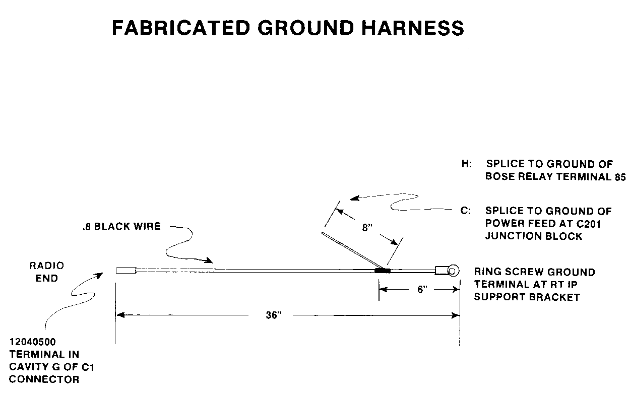
6. Make new ground harness per illustration using .8 black wire.
7. Install new ground harness radio end in cavity G of black connector (Cl). Reinstall black connector into back of radio. Route new ground wire with air conditioning/heater vacuum harness. Tie wire to vacuum harness to prevent rattles. Run to right side of instrument panel.
8. On LESABRE: Locate bose relay (Bosch style) behind glove box. Splice 8 inch long section of new ground harness to black ground wire of relay (terminal 85 and/or D of relay).
On ELECTRA: Attach 8 inch long section of new ground harness to radio power plug ground side at junction block C201. Locate correct power plug on left side of C201. Junction block (behind glove box). Radio power plug should be third from bottom. Remove old black ground wire at power plug and install new ground wire. Tape back removed ground wire.
9. Install new ground harness ring screw terminal end to 10mm bolt at right side instrument panel support bracket. Use external tooth lock washer to obtain good ground.
10. Connect battery. Torque terminals to 16-20 N.m (12-15 lb. ft.).
11. Install antenna connector at back of radio. Check operation of radio.
12. Install radio, trim plate, lower instrument panel, close out panel, and glove box.

General Motors bulletins are intended for use by professional technicians, not a "do-it-yourselfer". They are written to inform those technicians of conditions that may occur on some vehicles, or to provide information that could assist in the proper service of a vehicle. Properly trained technicians have the equipment, tools, safety instructions and know-how to do a job properly and safely. If a condition is described, do not assume that the bulletin applies to your vehicle, or that your vehicle will have that condition. See a General Motors dealer servicing your brand of General Motors vehicle for information on whether your vehicle may benefit from the information.
