IGNITION NOISE IN RADIO DIAGNOSIS AND REPAIR

MODELS AFFECTED: 1986 LESABRE AND ELECTRA NON-DELCO BOSE STEREO RADIO
A condition may exist on the 1986 LeSabre and Electra models equipped with stereo radio of ignition type electrical noise interference. The interference is engine speed related and disappears when engine is off. The interference may be due to the radio speaker wire routing in the instrument panel on the Electra, and ground wiring on the LeSabre.
The LeSabre electrical interference condition may be corrected by establishing a new ground point for the radio at the lower right side of the instrument panel. To correct the LeSabre, follow the procedure outlined for LeSabre with Delco Bose Radio in Service Bulletin No. 86-9-9. To correct the Electra ignition noise interference, perform the following:
1. Disconnect battery negative cable.
2. Remove instrument panel trim plate for access to radio, right lower instrument panel close out, and glove box.
3. Remove radio mounting screws and radio.
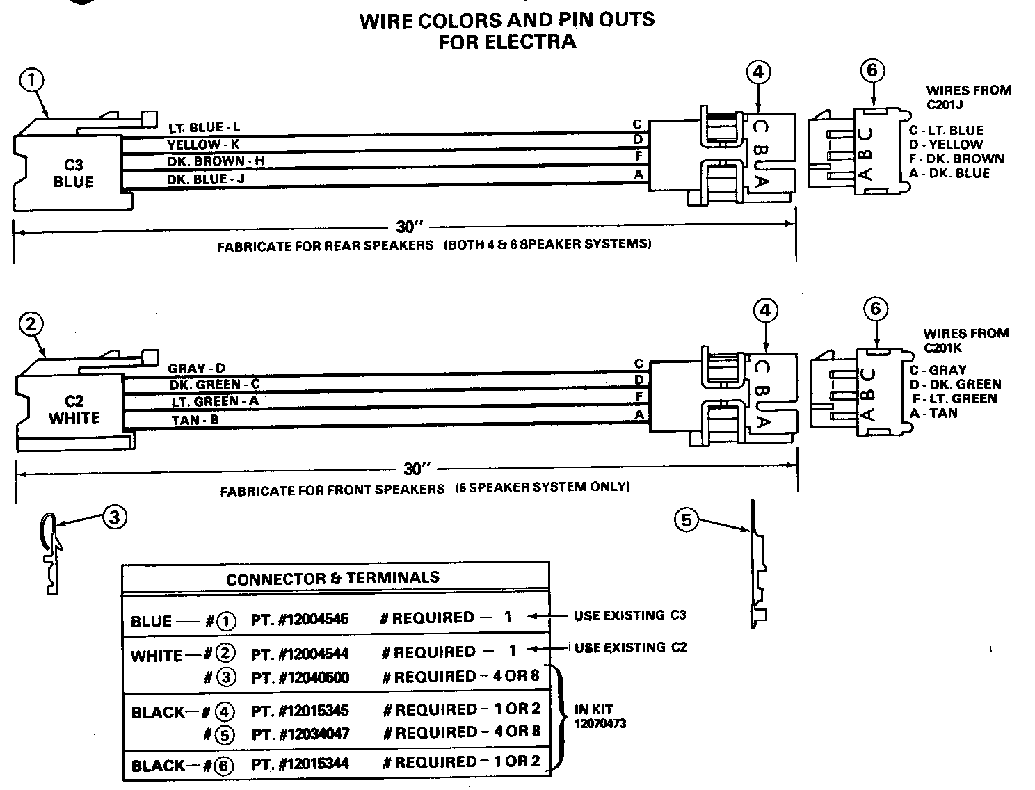
4. Depin terminals in connector C3 (blue color connector) for rear speakers.
5. On six speaker systems (Option UW6, Concert Sound Speaker System), depin terminals in connector C2 (White color connector) for front speakers.
6. Tape removed wires back to wiring harness to prevent rattles.
7. Fabricate 30 inch long leads (4 to 8, depending on whether connector C2 wires required removal). Install terminals 12040500 on one end of each wire, and terminal 12034047 on the other end using .8 wire. Terminals and connectors required for this modification may be obtained from a GMWDD Kit, Part Number 12070473.
8. Install 12040500 end of fabricated wires into connectors C2 and/or C3, as required. See Illustration. Install other end of wires in connector(s), Part Number 12015345. Make sure to maintain proper cavity orientation.
9. Remove connector(s) J, (black, rear speakers) and K (blue, front speakers) from right body junction block C201, as required. K only requires removal on a six speaker system.
10. Depin wires out of connector(s) J and K, as required, and install in connector(s) 12015344, per illustration.
11. Match connectors to appropriate front and/or rear fabricated harness.
12. Install new wiring harness(es) into back of radio. Route fabricated harness(es) along the Air Conditioning/Heater vacuum harness and secure to vacuum harness to prevent rattles. Install remaining radio connections.
13. Connect battery negative cable. Torque terminal to 16-20 N.m (12-15 lb. ft.).
14. Check operation of radio.
15. Install radio, trim plate, lower instrument panel close out and glove box.
MATERIAL REQUIRED
Electrical tape
Up to 20 feet of .8 wiring.
Connector and Terminal Kit No. 12070743 consisting of:
2 12015345 Connectors
2 12015344 Connectors
10 12040500 Terminals
10 12034047 Terminals
WARRANTY INFORMATION FOR ELECTRA
6 Speaker 4 Speaker System System ------ ------ LABOR OPERATION NUMBER: T5124 T5125 LABOR TIME: .8 .6 TROUBLE CODE: 92 92 MATERIAL ALLOWANCE: 1.75 1.00 (In addition to Connector and Terminal Kit 12070473).

General Motors bulletins are intended for use by professional technicians, not a "do-it-yourselfer". They are written to inform those technicians of conditions that may occur on some vehicles, or to provide information that could assist in the proper service of a vehicle. Properly trained technicians have the equipment, tools, safety instructions and know-how to do a job properly and safely. If a condition is described, do not assume that the bulletin applies to your vehicle, or that your vehicle will have that condition. See a General Motors dealer servicing your brand of General Motors vehicle for information on whether your vehicle may benefit from the information.
