Steering Linkage Inner Tie Rod Replacement - Off Vehicle Magnasteer
Special Tools
J 34028 Inner Tie Rod Wrench
Disassembly Procedure
- To remove the rack and pinion boot, refer to Steering Gear Boot and Breather Tube Replacement - Off Vehicle.
- Place the gear in a vise.
- Remove the shock dampener (6) from the inner tie rod housing (4).
- Slide the shock dampener (6) back on the rack (5).
- Place a pipe wrench on the rack (5) next to the inner tie rod housing (4).
- Place a wrench on the flats of the inner tie rod housing (4).
- Rotate the inner tie rod housing (4) counterclockwise, while holding the rack stationary, until the inner tie rod separates from the rack (5).
- Remove the shock dampener (3) from the inner tie rod housing (2).
- Slide the shock dampener (3) back on the rack (5).
- Place a pipe wrench on the rack.
- Place a wrench on the flats of the inner tie rod housing (2).
- Rotate the inner tie rod housing (2) counterclockwise, while holding the rack stationary, until the inner tie rod (1) separates from the rack (5).
- If female rack (1) and male inner tie rod (3), remove the old LOCTITE® from the threads (2) of the inner tie rod (3) and the rack (1).
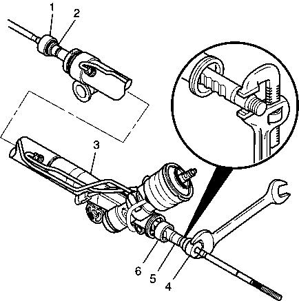
Important: After removing the boot, inspect the inner tie rod for evidence of corrosion or contamination. If none is evident, continue with the repair. If corrosion or contamination is evident, replace the steering gear.
Caution: Do not change the steering gear preload adjustment before moving the inner tie rod from the steering gear. Changing the steering gear preload adjustment before moving the inner tie rod could result in damage to the pinion and the steering gear.
Caution: The pipe wrench must be placed at the valve end of the steering gear and positioned up against the inner tie rod housing. Placing the pipe wrench in any other location will cause damage to the steering gear.
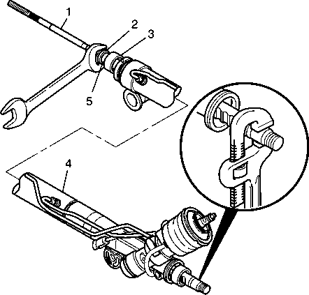
Caution: Refer to Pipe Wrench Positioning Caution in the Preface section.

If male rack (5) and female inner tie rod (4) LOCTITE® will not be present.
Assembly Procedure
- Slide the shock dampener (4) forward onto the rack (3).
- If female rack (3) and male inner tie rod (2), apply LOCTITE® 262, or equivalent, to the inner tie rod threads.
- Attach the inner tie rod onto the rack (3).
- Place a pipe wrench on the rack (3) next to the inner tie rod housing (2).
- Place a torque wrench and J 34028 on the flats of the inner tie rod housing (2).
- Slide the shock dampener (2) forward onto the rack.
- If female rack and male inner tie rod (1), apply LOCTITE® 262, or equivalent, to the inner tie rod threads.
- Attach the inner tie rod (1) onto the rack.
- Place a pipe wrench on the rack next to the inner tie rod housing (4).
- Place a torque wrench and J 34028 on the flats of the inner tie rod housing (7).
- Place the inner tie rod assembly (2) in a vise.
- Stake both sides of the female inner tie rod assembly housing to the male rack (1).
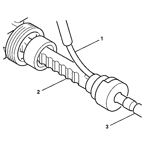
- Insert a 0.25 mm gage (1) between the rack (2) and the inner tie rod housing in order to check both stakes. The feeler gage (1) must not pass between the rack and the housing stake.
- Slide the shock dampener (2) over the inner tie rod housing (3) until the front lip of the shock dampener (2) bottoms against the inner tie rod housing (3).
- To assemble the rack and pinion boot. Refer to Steering Gear Boot and Breather Tube Replacement - Off Vehicle.
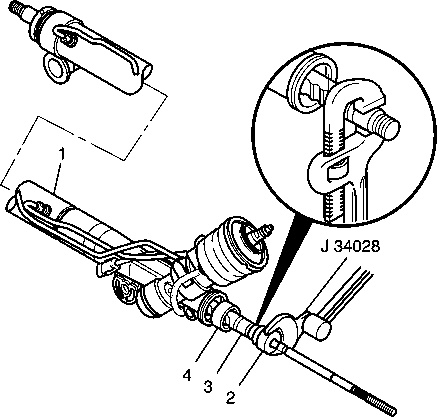
Note: Threads must be clean prior to LOCTITE® application. Check LOCTITE®, or equivalent, container for expiration date. Use only enough LOCTITE® to evenly coat threads.
If male rack (3) and female inner tie rod (2) do not apply LOCTITE®.Caution: Refer to Pipe Wrench Positioning Caution in the Preface section.
Caution: Refer to Fastener Caution in the Preface section.
Tighten
Tighten the inner tie rod to 100 N·m (74 lb ft).
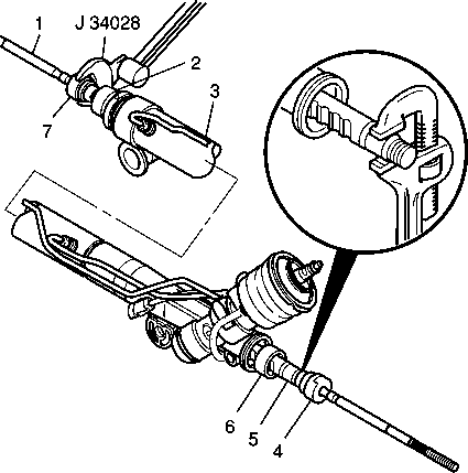
Note: Threads must be clean prior to LOCTITE® application. Check LOCTITE®, or equivalent, container for expiration date. Use only enough LOCTITE® to evenly coat threads.
If male rack and female inner tie rod (1) do not apply LOCTITE®.Caution: Refer to Pipe Wrench Positioning Caution in the Preface section.
Tighten
Tighten the inner tie rod to 100 N·m (74 lb ft).
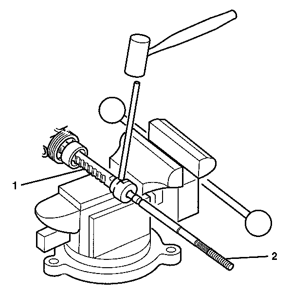
Note: If female rack (1) and male inner tie rod (2) do not stake. If male rack (1) and female inner tie rod (2) you must stake.

Steering Linkage Inner Tie Rod Replacement - Off Vehicle Quiet Valve
Disassembly Procedure
- Remove the rack and pinion boot. Refer to Steering Gear Boot and Breather Tube Replacement - Off Vehicle.
- Place the gear in a vise.
- Remove the shock dampener (4) from the inner tie rod assembly (6).
- Slide the shock dampener (4) back on the rack (5).
- Place a pipe wrench on the rack (5) next to the inner tie rod housing (6).
- Place a wrench on the flats of the inner tie rod housing (6).
- Rotate the inner tie rod housing (6) counterclockwise, while holding the rack stationary, until the inner tie rod separates from the rack (5).
- Remove the shock dampener (3) from the inner tie rod housing (2).
- Slide the shock dampener (3) back on the rack (5).
- Place a pipe wrench on the rack.
- Place a wrench on the flats of the inner tie rod housing (2).
- Rotate the inner tie rod housing (2) counterclockwise, while holding the rack stationary, until the inner tie rod (1) separates from the rack (5).
- If female rack (1) and male inner tie rod (3), remove the old LOCTITE® from the threads (2) of the inner tie rod and the rack.
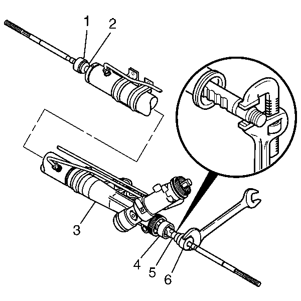
Note: After removing the boot, inspect the inner tie rod for evidence of corrosion or contamination. If none is evident, continue with the repair. If corrosion or contamination is evident, replace the steering gear.
Caution: Do not change the steering gear preload adjustment before moving the inner tie rod from the steering gear. Changing the steering gear preload adjustment before moving the inner tie rod could result in damage to the pinion and the steering gear.
Caution: Refer to Pipe Wrench Positioning Caution in the Preface section.
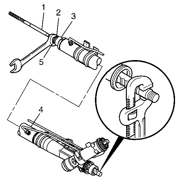

If male rack (5) and female inner tie rod (4) LOCTITE® will not be present.
Assembly Procedure
- Slide the shock dampener (4) forward onto the rack (3).
- If female rack (3) and male inner tie rod (2), apply LOCTITE® 262 or equivalent to the inner tie rod threads.
- Attach the inner tie rod onto the rack (3).
- Place a pipe wrench on the rack (3) next to the inner tie rod housing (2).
- Place a torque wrench and J 34028 on the flats of the inner tie rod housing (2).
- Slide the shock dampener (2) forward onto the rack.
- If female rack and male inner tie rod (1), apply LOCTITE® 262 or equivalent to the inner tie rod threads.
- Attach the inner tie rod (1) onto the rack.
- Place a pipe wrench on the rack next to the inner tie rod housing (4).
- Place a torque wrench and J 34028 on the flats of the inner tie rod housing (7).
- Place the inner tie rod assembly (2) in a vise.
- Stake both sides of the female inner tie rod assembly housing to the male rack.
- Insert a 0.25 mm gage (1) between the rack (2) and the inner tie rod housing in order to check both stakes. The feeler gage (1) must not pass between the rack and the housing stake.
- Slide the shock dampener (2) over the inner tie rod housing (3) until the front lip of the shock dampener (2) bottoms against the inner tie rod housing (3).
- To assemble the rack and pinion boot. Refer to Steering Gear Boot and Breather Tube Replacement - Off Vehicle.
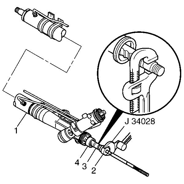
Note: Threads must be clean prior to LOCTITE® application. Check LOCTITE® or equivalent container for expiration date. Use only enough LOCTITE® to evenly coat threads.
If male rack (3) and female inner tie rod (2) do not apply LOCTITE®.Caution: Refer to Pipe Wrench Positioning Caution in the Preface section.
Caution: Refer to Fastener Caution in the Preface section.
Tighten
Tighten the inner tie rod to 100 N·m (74 lb ft).

Note: Threads must be clean prior to LOCTITE® application. Check LOCTITE® or equivalent container for expiration date. Use only enough LOCTITE® to evenly coat threads.
If male rack and female inner tie rod (1) do not apply LOCTITE®.Caution: Refer to Title not found in the Preface section.
Tighten
Tighten the inner tie rod to 100 N·m (74 lb ft).

Note: If female rack (1) and male inner tie rod (2) do not stake. If male rack (1) and female inner tie rod (2) you must stake.


