Automatic Transmission Shift Lock Control Actuator Replacement Floor Shift
Removal Procedure
- Disconnect the negative battery cable. Refer to
Battery Negative Cable Disconnection and Connection
in Engine
Electrical.
- Remove the center console. Refer to
Front Floor Console Replacement
in Instrument Panel, Gages and
Console.

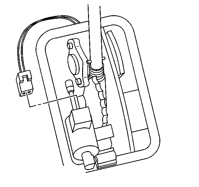
- Disconnect electrical
connector from the shift lock control for the automatic transmission (AT).

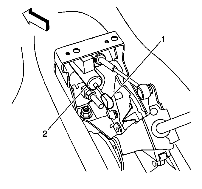
- Remove both ends of the
AT shift lock control from pivot points (1).
Installation Procedure

- Install the upper clip (1)
of the AT shift lock control onto the upper pivot point, and the lower clip
onto the lower pivot point.
- Connect the electrical connector to the AT shift lock control.
- Install the center console. Refer to
Front Floor Console Replacement
in Instrument Panel, Gages and
Console.
- Connect the negative battery cable. Refer to
Battery Negative Cable Disconnection and Connection
in Engine
Electrical.
Automatic Transmission Shift Lock Control Actuator Replacement Column Shift
Removal Procedure

- Remove the knee bolster.
Refer to
Knee Bolster Replacement
in Instrument Panel, Gages
and Console.
- Disconnect the electrical connector from the automatic shift lock
control actuator.
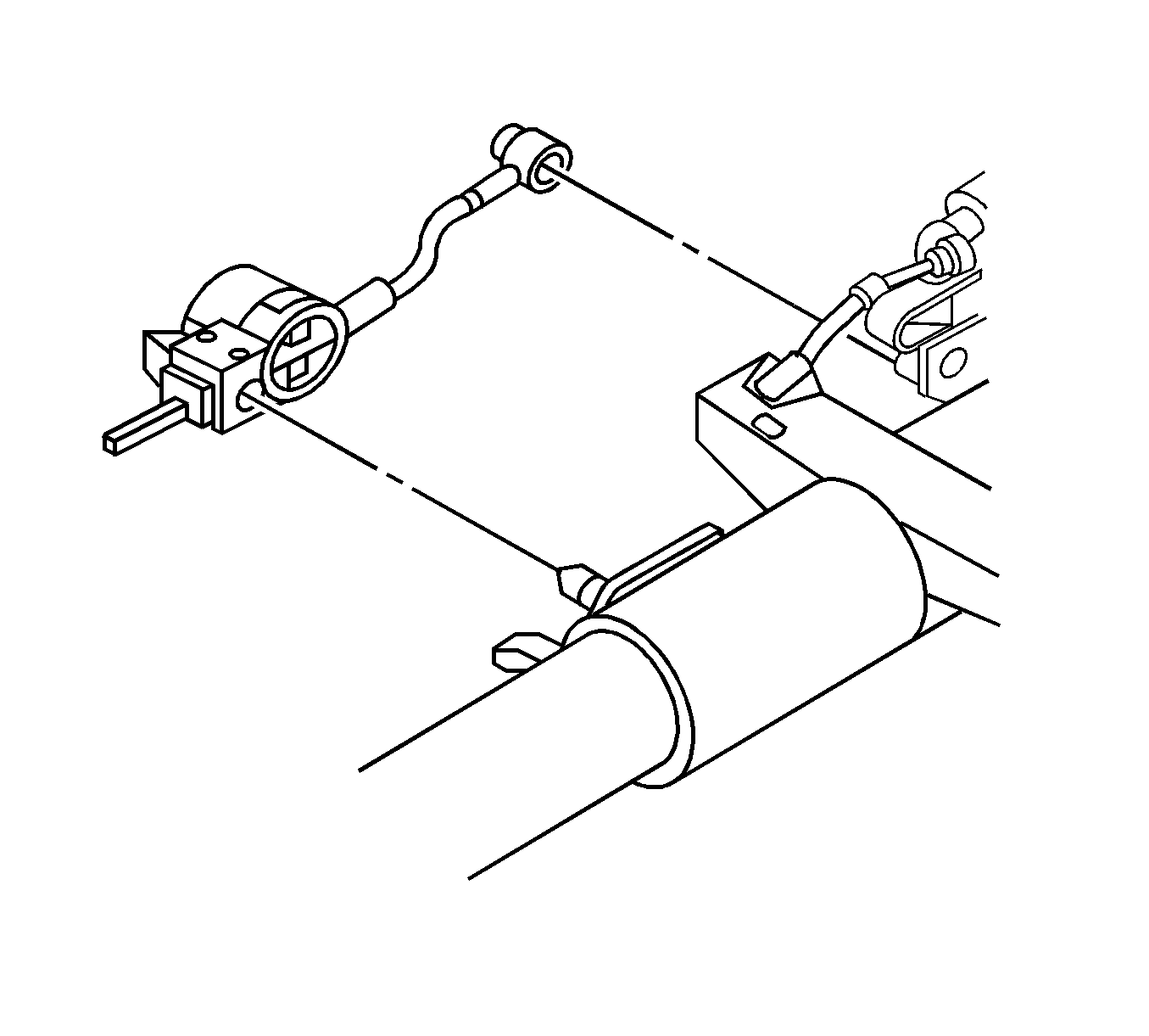
- Remove the automatic shift lock control actuator from the steering
column ball studs.
Installation Procedure

- Install the automatic
shift lock control actuator onto the steering column ball studs.
- Connect the electrical connector to the automatic shift lock control
actuator.

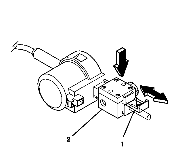
- Adjust the automatic shift
lock control actuator.
| • | Pull out the tab (1) on the adjuster block side (2)
of the actuator. |
| • | Press on the adjuster block (2) in order to compress the
internal adjuster spring and disengage the adjuster teeth. Slide the adjuster
block as far away from the actuator as possible. |
| • | Lock in place by pushing in on the tab (1). |
- Inspect the actuator.
| • | The actuator must lock the shift lever clevis when you place the
clevis in the park position. |
| • | If you can move the shift lever without pressing on the brake
pedal, readjust the actuator. |
- Install the knee bolster. Refer to
Knee Bolster Replacement
in Instrument Panel, Gages and Console.


