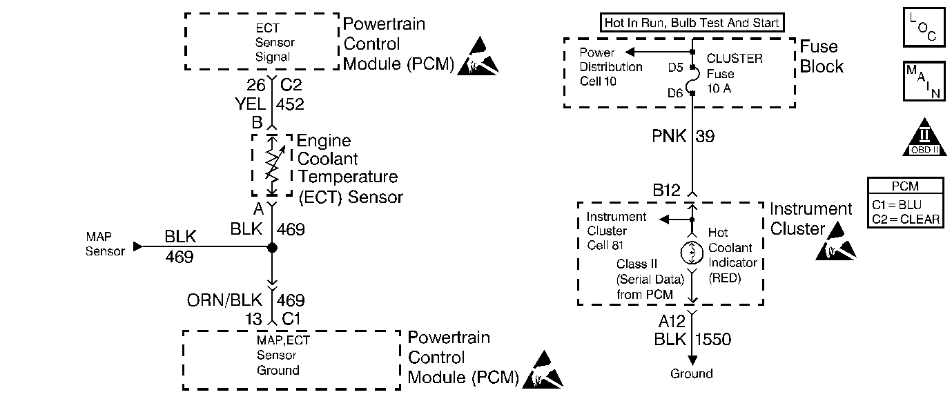
Circuit Description
To provide the best possible combination of driveability, fuel economy, and emission control, a closed loop air/fuel system is used. The PCM monitors inputs from various sensors to adjust fuel delivery, and spark timing. When a high engine coolant temperature is detected, the PCM may enter a Hot Fuel Enrichment (HFE) mode. During HFE, a richer air/fuel ratio is commanded which can cause exhaust emissions to exceed the federal emissions standards. The PCM calculates an engine coolant temperature value based on intake air temperature, engine speed, vehicle speed, and engine load. The PCM compares the calculated value to the actual ECT sensor signal input. If the ECT sensor signal input is higher than the calculated coolant temperature value, due to a skewed ECT or IAT sensor signal or an actual hot engine condition, DTC P1483 will set and the PCM will disable HFE.
Conditions for Running the DTC
| • | No MAF, MAP, ECT, or VSS sensor DTCs are set. |
| • | Key on engine coolant temperature is the same or less than 110°C. |
| OR |
| • | The engine coolant temperature goes less than 104°C anytime after key on. |
| • | Intake Air Temperature, Engine Load, Engine Speed and Vehicle Speed are all within a specific range. |
Conditions for Setting the DTC
The PCM detects a higher engine coolant temperature than the calculated coolant temperature.
Action Taken When the DTC Sets
| • | The Malfunction Indicator Lamp (MIL) will not illuminate. |
| • | No message will be displayed. |
Conditions for Clearing the MIL/DTC
| • | A History DTC will clear after forty consecutive warm-up cycles with no failures of any non-emission related diagnostic test. |
| • | A Last Test Failed (current) DTC will clear when the diagnostic runs and does not fail. |
| • | PCM battery voltage is interrupted. |
| • | Using a Scan tool. |
Diagnostic Aids
The most likely cause of this DTC is a cooling system problem. Perform the Electric Cooling Fan Diagnosis in this section and also visually inspect the cooling system for problems such as restricted radiator airflow.
Test Description
The number(s) below refer to the step number(s) on the diagnostic table:
-
It is critical that the sensors are accurate to within 1 degree. The engine must be allowed to cool completely. Depending on conditions this will take a minimum of 6 hours.
-
The IAT sensor must indicate the actual ambient temperature to within 1 degree. If the IAT sensor is accurate the ECT sensor must be inaccurate.
Further checks of the ECT sensor can be made by comparing actual coolant temperature to the ECT scan tool display.
Obtain actual coolant temperature using a thermometer located in the engine coolant. A check of the ECT sensor's resistance may also be performed using the Temperature Versus Resistance Specifications table.
If the actual coolant temperature is the same as the ECT scan tool display then the engine was not allowed to cool completely. Allow the vehicle to cool and repeat the diagnostic table.
Step | Action | Value(s) | Yes | No |
|---|---|---|---|---|
1 | Was the Powertrain On Board Diagnostic (OBD) System Check Check performed? | -- | Go to Step 2 | |
2 | Are any other DTCs set? | -- | Go to DTCs that are set | Go to Step 3 |
Verify proper operation of the ECT and IAT sensor by performing the following:
Allowing the vehicle to stabilize overnight will ensure the most accurate results. Using a scan tool compare the ECT and IAT sensors. If both sensors do not indicate exactly the same temperature one of the sensors is inaccurate. Do both sensors indicate the same temperature? | -- | Go to Diagnostic Aids | Go to Step 4 | |
Allow the thermometer temperature to stabilize. Refer to Test Descriptions. Is the IAT sensor responding correctly to actual ambient temperature? | -- | Go to Step 5 | Go to Step 6 | |
5 | Replace the ECT sensor. Refer to Engine Coolant Temperature Sensor Replacement . Is the repair complete? | -- | Go to Powertrain Control Module Diagnosis | -- |
6 | Replace the IAT sensor. Refer to Intake Air Temperature Sensor Replacement . Is the replacement complete? | -- | Go to Powertrain Control Module Diagnosis | -- |
