REVISED: V-5 A/C COMPRESSOR FRT. HEAD TO CYL. O-RING P/N

MODELS AFFECTED: 1985-86 SKYHAWK, 2.0L (P) ---------------- 1986 SKYHAWK, 1.8L (0) 1985-86 SOMERSET, 2.5L (U) 1986 SKYLARK, 2.5L (U) 1986 CENTURY, 2.5L (R)
NOTE: This bulletin information supersedes Service Bulletin 85-I-16, dated February, 1985.
The return program involving V-5 air conditioning compressors terminated September 1, 1985. Some service compressors, however, still contain information regarding the return program. This return information should be disregarded.
When repairing the V-5 compressor, it is suggested that you use the diagnostics contained in the 1986 Chassis Service Manual. The 1986 diagnostics are improved over the 1985 Chassis Service Manual, but will also pertain to the 1985 model. It is suggested that a notation be made in your 1985 Chassis Service Manual to refer to the diagnostic charts on pages 1B-10 and 1B-11 of the 1986 Chassis Service Manual.
A number of compressors have been replaced that only have a defective control valve. An additional diagnostic procedure for evaluating inadequate system cooling due to the control valve follows:
A. Check for:
1. Blown A/C fuse and/or gage fuse.
2. Loose or disconnected A/C wire connector.
3. Check blower for fan operation.
4. Engine cooling fan operation, fan operates in all A/C modes as follows :
a. Disconnect engine coolant temperature fan switch.
b. With ignition in on position and engine not running, set A/C control to A/C mode.
c. Engine cooling fan should run.
d. Reconnect engine coolant temperature fan switch.
B. Check that the compressor drive belt is not loose, missing or damaged, and that compressor is not seized.
C. With ambient temperature above 50 DEG F. (10 DEG C), check for compressor clutch engagement as follows:
1. Engine running (approximately 1000 rpm).
2. Set A/C control to 'NORM' and 'HIGH' blower.
3. Put auxiliary fan in front of vehicle.
4. Observe clutch operation for five minutes.
D. If clutch engages, but does not cycle, install high and low pressure gages. If both gages read within 10 psi of each other:
1. Discharge system.
2. Remove and replace compressor control valve.
3. Evacuate and charge system.
4. If problem persists, replace compressor pump assembly.
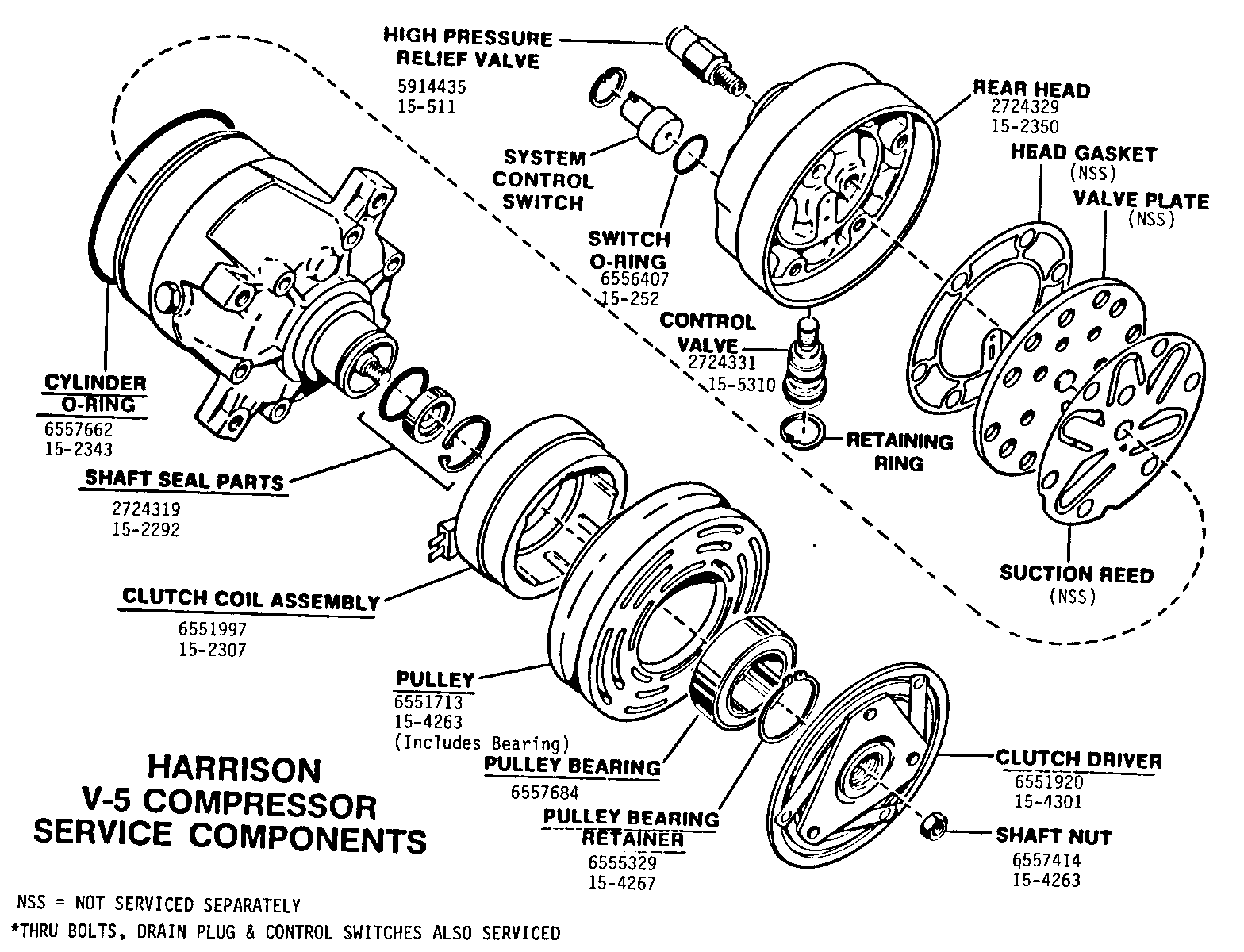
For your convenience, attached is a Service Parts Listing for the V-5 compressor models currently released, along with a labeled exploded V-5 compressor view.
COMPRESSOR PART NUMBER CHART
HARRISON GMWDD PART NUMBER PART NUMBER MODEL USAGE ----------- ----------- ----------- 1986 Skyhawk With 1131543 12323441 1.8L Engine (0)
1985-86 Skyhawk 1131451 12322147 With 2.0L Engine (P)
1985-86 Somerset & 1131441 12322146 1986 Skylark With L.5L engine (U)
1986 Century With 1131515 12323436 2.5L Engine (R)
V-5 COMPRESSOR SERVICE PARTS LIST
COMPRESSOR MODEL NO. PART NO. PART NO. (STAMPED ON COMPRESSOR-SERVICE QTY W/O CLUTCH W/CLUTCH COMPRESSOR) ------------------ --- ---------- -------- ----------- 85-86 Models W/2.5L Engine (U & R) 1 2724327 12322146 1131441 12323436 1131515
85-86 Models W/2.0L Engine (P) 1 2724328 12322147 1131451
86 Models W/1.8L Engine (0) 1 2724345 12323441 1131543
Head, Compressor, Rear, Kit - 2 Switch Type 2724329 All Includes: Head Rear (NAS) 1 O-Ring, Head 1 Gasket, Bolt (NAS) 6 Gasket, Rear Head (NAS) 1 O-Rings Kit, Control Valve 1 Ring, Retainer-Switch 2 O-Ring, Switch 2 Instruction Sheet (NAS) 1
O-Rings & Retainer-Control Valve Kit 2724330 All Includes: O-Rings 4 Ring, Retainer 1
O-Ring, Rear Head 1 6557662 All
Control Valve Assembly Kit 2724331 All Includes: Control Valve Assembly (NAS) 1 Ring Retainer 1
Thru Bolts and Gasket Kit 2724332 Includes: Thru Bolts (NAS) 6 Bolt Gasket 6
Gasket Thru Bolts 6 6557379 All Plug and Washer Assy. Drain 1 6557638 All Seal, Shaft Kit 2724319 All Includes: Seal, Lip (NAS) 1 O-Ring, Seal Seat (NAS) 1 Ring, Retainer 1 Instruction Sheet (NAS) 1
*Switch, HPCO (3.0 AMP) Kit 2724333 1131441 1131515 1131543
*Switch, HPCO (11.6 MA) Kit 2724335 1131451
*Switch, HSLP (3.0 AMP) Kit 2724334 1131441 1131515 1131543
*Switch, HSLP (11.6 MA) Kit 2724336 1131451 *Above Switch Kits Include: O-Ring Switch 1 Ring Retainer 1
Coil and Housing Assy. Clutch 1 6551997 All
Pulley Rotor & Bearing Assy. 1 6551713 All
Bearing, Pulley 1 6557684 All
Ring, Retainer-Bearing 1 6555329 All
Clutch Driver Assembly 1 6551920 All
Key, Clutch Hub 1 6555320 All
Nut, Shaft 1 6557414 All
Valve, High Pressure Relief & O-Ring 1 5914435 All
O-Ring HPRV (5/PKG.) 1 6555437 All
O-Ring, Suction -
Discharge (5/PKG.) 1 5887997 All
Oil, 525 Viscosity QT 5416939 All
NOTE: NAS - NOT AVAILABLE SEPARATELY

General Motors bulletins are intended for use by professional technicians, not a "do-it-yourselfer". They are written to inform those technicians of conditions that may occur on some vehicles, or to provide information that could assist in the proper service of a vehicle. Properly trained technicians have the equipment, tools, safety instructions and know-how to do a job properly and safely. If a condition is described, do not assume that the bulletin applies to your vehicle, or that your vehicle will have that condition. See a General Motors dealer servicing your brand of General Motors vehicle for information on whether your vehicle may benefit from the information.
