NO START / NO RUN BLOWN FUEL PUMP FUSE

Models Affected: 1984 2.0L Engine (Vin Code P) and all 1985 TBI Engines (Vin Codes O,P,R and U)
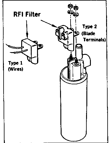
Some models may experience a no run or no start condition, and/or blown fuel pump fuse due to an inoperative In-Tank Electric Fuel Pump, which may be due to a short in the radio frequency interence (RFI) filter. The RFI filter is located on the electrical input terminals of the in-tank electric fuel pump. (See Figure).
To check, disconnect the three wire connector at the fuel tank and measure the resistance between the two outside wires of the connector going to the tank (black and tan). A resistance measurement of 3 to 4 ohms indicates a good unit.
To check further, remove the tank unit assembly and measure the resistance of the RFI filter and pump assembly individually.
Resistance of good RFI filter - infinity (open circuit).
Resistance of good pump assembly - 3 to 4 ohms.
If the RFI filter is shorted, replace filter with the following kit.
Part Number Information 1984 - 6472781 1985 - 6472779
If the fuel pump is inoperative, replace pump with appropriate part number for vehicle being serviced.
RFI FILTER REPLACEMENT - PROCEDURE
1. Cut-off rubber coupler and discard.
2. If RFI filter has blade type electrical terminals disconnect wires from terminals of RFI filter. Note which terminal is the ground (-) connection. Polarity markings (+ or -) are molded inside the top of the pump plastic cap near each terminal. (See Figure - Type 2).
If RFI filter has electrical wires molded into it. Cut ground (-) between RFI filter and terminal 11/2 inches from terminal end of wire and strip ground (-) wire back 16mm (5/8 inch) . Disconnect power supply (+) wire of RFI filter from feed through connector at assembly cover (See Figure - Type 1).
3. Unscrew the nuts at the pump terminals and remove the RFI filter.
4. When installing new RFI filter with electrical wires molded into it, (Type 1), first remove the pump from the sender assembly, as it may contain combustible gasoline vapors. Splice the ground (-) wire on the RFI filter to the cut off wire remaining on the sender assembly by twisting and soldering the wires together. Reinstall the pump on the sender assembly.
5. Install the new RFI filter on the pump using the nuts and lockwashers provided. Torque the nuts 0.56 to 1.13 N.m (5 to 10 lbs.in.). Caution: Use of excessive torque will strip the pump threaded terminals.
6. If RFI filter has blade type electrical terminals, (Type 2), reconnect power and ground wires to the blade type terminals observing proper polarity. (See step 2).
7. Lubricate the fuel tube and pump outlet tube with a small amount of white petroleum jelly. Slide the new rubber coupler on the fuel tube.
8. Align the pump outlet and fuel tube then push the coupler down over the pump outlet. Caution: Support the bracket to prevent it from bending while sliding the rubber coupler into position.
9. Inspect pump to assure that it is properly seated into the bracket and properly wired. An improperly wired pump will run backwards but will not pump fuel. Caution: Do not run pump dry.

General Motors bulletins are intended for use by professional technicians, not a "do-it-yourselfer". They are written to inform those technicians of conditions that may occur on some vehicles, or to provide information that could assist in the proper service of a vehicle. Properly trained technicians have the equipment, tools, safety instructions and know-how to do a job properly and safely. If a condition is described, do not assume that the bulletin applies to your vehicle, or that your vehicle will have that condition. See a General Motors dealer servicing your brand of General Motors vehicle for information on whether your vehicle may benefit from the information.
