Customer Satisfaction - Modification to Improve Side Impact Protection

| Subject: | 07003B -- Modification to Improve Side Impact Protection |
| Models: | 2007 Buick Allure, LaCrosse |
The service procedure and claim information sections in this bulletin have been revised to include an inspection procedure and labor code. There may be a few vehicles that were repaired before shipment to dealerships. Please discard all copies of bulletin 07003A, issued March 2007.
Condition
2007 model year Buick Allure and LaCrosse vehicles not only meet, but exceed government standards for side impact protection. GM recently introduced into production, changes that add to that protection, including a revised wiring harness that provides a more protected path for the wires that send the signal to inflate the side impact airbag. GM is making similar changes to vehicles built before the production change.
Correction
To enhance the side impact protection, dealers are to modify both front door panels and install additional energy-absorbing material, if necessary, and also update the wiring harness in the door. The wiring harness update provides a more protected path for the wires that send the signal to inflate the side impact airbag. Without this wiring harness update, under certain crash conditions, the side impact airbag may not deploy.
Vehicles Involved
Involved are certain 2007 Buick Allure and LaCrosse vehicles built within these VIN breakpoints:
Year | Division | Model | From | Through |
|---|---|---|---|---|
2007 | Buick | Allure | 71100036 | 71201597 |
2007 | Buick | LaCrosse | 71100006 | 71210249 |
Important: Dealers are to confirm vehicle eligibility prior to beginning repairs by using GMVIS. Not all vehicles within the above breakpoints may be involved.
For dealers with involved vehicles, a listing with involved vehicles containing the complete vehicle identification number, customer name, and address information has been prepared and will be provided through the applicable system listed below. Dealers will not have a report available if they have no involved vehicles currently assigned.
-- US dealers - GM DealerWorld Recall Information
-- Canadian dealers - GMinfoNet Recall Reports
-- Export dealers - sent directly to dealers
The listing may contain customer names and addresses obtained from Motor Vehicle Registration Records. The use of such motor vehicle registration data for any purpose other than follow-up necessary to complete this program is a violation of law in several states/provinces/countries. Accordingly, you are urged to limit the use of this report to the follow-up necessary to complete this program.
Parts Information
Parts required to complete this program are to be obtained from General Motors Service and Parts Operations (GMSPO). Please refer to your "involved vehicles listing" before ordering parts. Normal orders should be placed on a DRO = Daily Replenishment Order. In an emergency situation, parts should be ordered on a CSO = Customer Special Order.
Part Number | Description | Qty/ Vehicle |
|---|---|---|
25848978 | Absorber Asm, Frt S/D Inr Pnl Lwr Engy (RH) | 1 (If Req'd) |
25848979 | Absorber Asm, Frt S/D Inr Pnl Lwr Engy (LH) | 1 (If Req'd) |
25850945 | Absorber, Frt S/D T/Pnl Engy (LH) | 1 (If Req'd) |
25850946 | Absorber, Frt S/D T/Pnl Engy (RH) | 1 (If Req'd) |
25862778 | Harness Asm, Infl Rst Wrg | 2 (If Req'd) |
Service Procedure
Tools Required
J 38778 Door Trim Pad Clip Remover
Caution: When performing service on or near the supplemental inflatable restraint (SIR) components or the SIR wiring, the SIR system must be disabled. Failure to observe the correct procedure could cause deployment of the SIR components. Serious injury can occur. Failure to observe the correct procedure could also result in unnecessary SIR system repairs.
Caution: Do not strike or jolt the inflatable restraint side impact sensor (SIS). Before applying power to the SIS make sure that it is securely fastened. Failure to observe the correct installation procedures could cause SIR deployment, personal injury, or unnecessary SIR system repairs.
The inflatable restraint sensing and diagnostic module (SDM) maintains a reserved energy supply. The reserved energy supply provides deployment power for the airbags if the SDM loses battery power during a collision. Deployment power is available for as much as 1 minute after disconnecting the vehicle power. Waiting 1 minute before working on the system after disabling the SIR system prevents deployment of the airbags from the reserved energy supply.
Important: Skip Steps 17.0-17.24 if the vehicle is NOT equipped with roof-mounted side impact air bags. Vehicles without roof-mounted side impact airbags will NOT have the side impact sensor (SIS) harness. Review and complete the door trim panel and door energy absorber block service procedure in this bulletin.
Important: Perform this procedure on both the driver and passenger side front side door.
- Disable the SIR system. Refer to SIR Disabling and Enabling in SI.
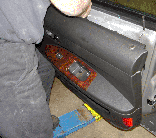
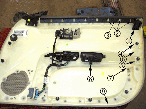
- Remove the front side door trim panel. Refer to Front Side Door Trim Panel Replacement in SI.
- Inspect the water deflector to determine if two of the three foam blocks (1) have been removed from the water deflector.
Water Deflector with Two Foam Blocks
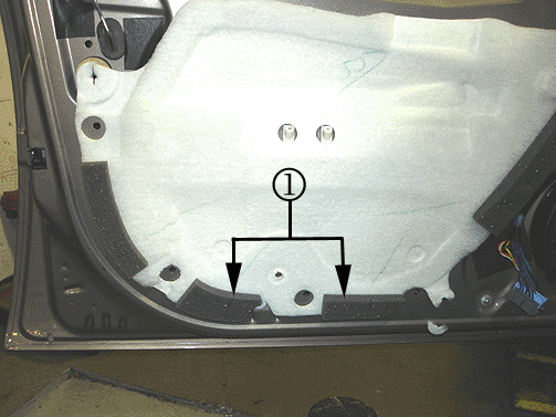
Water Deflector without Two Foam Blocks
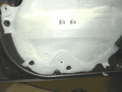
| • | If the two foam blocks have been removed from the water deflector, the door trim modifications and the energy absorber blocks have been installed. Proceed to Step 16. |
| • | If the two foam blocks have NOT been removed from the water deflector, proceed to Step 4. |
Courtesy Transportation - For US and Canada
The General Motors Courtesy Transportation program is intended to minimize customer inconvenience when a vehicle requires a repair that is covered by the New Vehicle Limited Warranty. The availability of courtesy transportation to customers whose vehicles are within the warranty coverage period and involved in a product program is very important in maintaining customer satisfaction. Dealers are to ensure that these customers understand that shuttle service or some other form of courtesy transportation is available and will be provided at no charge. Dealers should refer to the General Motors Service Policies and Procedures Manual for Courtesy Transportation guidelines.
Claim Information
Submit a Product Claim with the information indicated below:
Repair Performed | Part Count | Part No. | Parts Allow | CC-FC | Labor Op | Labor Hours |
|---|---|---|---|---|---|---|
Door Inspection - No Repair Required | N/A | N/A | N/A | MA-96 | V1597 | 0.7 |
Modify Doors, Install Energy-Absorbing Material & Perform Door Wire Harness Update | 6 | -- | * | MA-96 | V1555 | 2.6 |
Perform Door Wire Harness Update Only | 2 | -- | ** | MA-96 | V1567 | 2.0 |
Modify Doors and Install Energy-Absorbing Material | 4 | -- | *** | MA-96 | V1587 | 1.8 |
Courtesy Transportation for vehicles within the New Vehicle Limited Warranty (US & Canadian GM Dealers) | N/A | N/A | N/A | MA-96 | **** | N/A |
* The "Parts Allowance" should be the sum total of the current GMSPO Dealer net price plus applicable Mark-Up or Landed Cost Mark-Up (for Export) for the absorbers, absorber assemblies, and harness assemblies needed to complete the repair. ** The "Parts Allowance" should be the sum total of the current GMSPO Dealer net price plus applicable Mark-Up or Landed Cost Mark-Up (for Export) for the harness assemblies needed to complete the repair. *** The "Parts Allowance" should be the sum total of the current GMSPO Dealer Net price plus applicable Mark-Up or Landed Cost Mark-Up (for Export) for the absorbers and absorber assemblies needed to complete the repair. **** Submit courtesy transportation using normal labor operations for courtesy transportation as indicated in the GM Service Policies and Procedures Manual for vehicles within the New Vehicle Limited Warranty. | ||||||
Refer to the General Motors WINS Claims Processing Manual for details on Product Recall Claim Submission.
Customer Notification - For US and Canada
General Motors will notify customers of this program on their vehicle (see copy of customer letter included with this bulletin).
Customer Notification - For Export
Letters will be sent to known owners of record located within areas covered by the US National Traffic and Motor Vehicle Safety Act. For owners outside these areas, dealers should notify customers using the attached sample letter.
Dealer Recall Responsibility
All unsold new vehicles in dealers' possession and subject to this program must be held and inspected/repaired per the service procedure of this program bulletin before customers take possession of these vehicles.
Dealers are to service all vehicles subject to this program at no charge to customers, regardless of mileage, age of vehicle, or ownership, from this time forward.
Customers who have recently purchased vehicles sold from your vehicle inventory, and for which there is no customer information indicated on the dealer listing, are to be contacted by the dealer. Arrangements are to be made to make the required correction according to the instructions contained in this bulletin. A copy of the customer letter is provided in this bulletin for your use in contacting customers. Program follow-up cards should not be used for this purpose, since the customer may not as yet have received the notification letter.
In summary, whenever a vehicle subject to this program enters your vehicle inventory, or is in your dealership for service in the future, you must take the steps necessary to be sure the program correction has been made before selling or releasing the vehicle.
March 2007 (letter for customers requiring the door modification, installation of the energy-absorbing material, and the wire harness update)Dear General Motors Customer:
This notice is sent to inform you that Buick is conducting a customer satisfaction program that affects certain 2007 model year Buick Allure and LaCrosse vehicles.
Your 2007 model year Buick Allure or LaCrosse vehicle not only meets, but exceeds government standards for side impact protection. GM recently introduced into production, changes that add to that protection. At no charge, your dealer will make similar changes to your vehicle, which was built before the production change.
What We Will Do: To enhance the side impact protection, your Buick dealer will modify both front door panels, install additional energy-absorbing material, and update the wiring harness in the door. This service will be performed for you at no charge .
What You Should Do: To limit any possible inconvenience, we recommend that you contact your Buick dealer as soon as possible to schedule an appointment for this repair. By scheduling an appointment, your dealer can ensure that the necessary parts will be available on your scheduled appointment date
Customer Reply Form: The enclosed customer reply form identifies your vehicle. Presentation of this form to your dealer will assist in making the necessary correction in the shortest possible time. If you no longer own this vehicle, please let us know by completing the form and mailing it back to us.
If you have any questions or need any assistance, just contact your dealer or the appropriate Customer Assistance Center at the number listed below. The Customer Assistance Center’s hours are 8:00 AM - 11:00 PM, EST, Monday through Friday.
Division | Number | Text Telephones (TTY) |
|---|---|---|
Buick | 1-866-608-8080 | 1-800-832-8425 |
Guam | 1-671-648-8650 |
|
Puerto Rico - English | 1-800-496-9992 |
|
Puerto Rico - Español | 1-800-496-9993 |
|
Virgin Islands | 1-800-496-9994 |
|
Courtesy Transportation: If your vehicle is within the New Vehicle Limited Warranty your dealer may provide you with shuttle service or some other form of courtesy transportation while your vehicle is at the dealership for this repair. Please refer to your Owner’s Manual and your dealer for details on courtesy transportation.
We sincerely regret any inconvenience or concern that this situation may cause you. We want you to know that we will do our best, throughout your ownership experience, to ensure that your GM vehicle provides you with many miles of enjoyable driving.
Scott Lawson
General Director,
Customer and Relationship Services
Enclosure
07003
March 2007 (Letter for customers requiring only the wire harness update)Dear General Motors Customer:
This notice is sent to inform you that Buick is conducting a customer satisfaction program that affects certain 2007 model year Buick Allure and LaCrosse vehicles.
Your 2007 model year Buick Allure or LaCrosse vehicle not only meets, but exceeds government standards for side impact protection.
Why We Are Taking This Action: GM recently introduced into production, changes that add to that protection, including a revised wiring harness that provides a more protected path for the wires that send the signal to inflate the side impact airbag. Without this wiring harness update, under certain crash conditions, your side impact airbag may not deploy.
What We Will Do: To enhance the side impact protection, your Buick dealer will make similar changes to your vehicle. This service will be performed for you at no charge.
What You Should Do: To limit any possible inconvenience, we recommend that you contact your Buick dealer as soon as possible to schedule an appointment for this repair. By scheduling an appointment, your dealer can ensure that the necessary parts will be available on your scheduled appointment date.
Customer Reply Form: The enclosed customer reply form identifies your vehicle. Presentation of this form to your dealer will assist in making the necessary correction in the shortest possible time. If you no longer own this vehicle, please let us know by completing the form and mailing it back to us.
If you have any questions or need any assistance, just contact your dealer or the appropriate Customer Assistance Center at the number listed below. The Customer Assistance Center’s hours are 8:00 AM - 11:00 PM, EST, Monday through Friday.
Division | Number | Text Telephones (TTY) |
|---|---|---|
Buick | 1-866-608-8080 | 1-800-832-8425 |
Guam | 1-671-648-8650 |
|
Puerto Rico - English | 1-800-496-9992 |
|
Puerto Rico - Español | 1-800-496-9993 |
|
Virgin Islands | 1-800-496-9994 |
|
Courtesy Transportation: If your vehicle is within the New Vehicle Limited Warranty your dealer may provide you with shuttle service or some other form of courtesy transportation while your vehicle is at the dealership for this repair. Please refer to your Owner’s Manual and your dealer for details on courtesy transportation.
We sincerely regret any inconvenience or concern that this situation may cause you. We want you to know that we will do our best, throughout your ownership experience, to ensure that your GM vehicle provides you with many miles of enjoyable driving.
Scott Lawson
General Director,
Customer and Relationship Service
Enclosure
07003
